


31
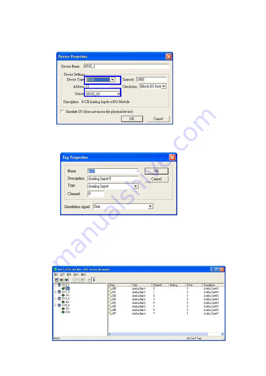
5. Type the “Device Name” and select the “Device Type” and the “Driver” in the “Device
Properties” window. Device Type means the JetI/O model name. Driver is the name
you configured in last step.
6. Select “Add -> New Group” to create new group for the later new tags you’ll create.
Select “Add -> New Tag” and fill the “Tag Properties” in the popup window. Select the
tag and “Edit –> Properties“, you can modify the tag properties.
Note: The Simulation Signal is used when choosing Simulate I/O mode. Simulate I/O mode is
selected in “Device Properties”. This feature allows you to generate simulation values and run
testing when you operate the OPC client. You can see the value is continuously changed. The Sine,
Ramp and Random are the different type’s simulation signal.
7. Select the device in the device list. Choose “Add -> Generate Tags”, the utility
generate all the channels’ tags for the device you choose. This step can save the time
to create all channels’ tags.


