background image


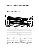
11 

right-front-down 
box lid   

box lid   

41

center lid 


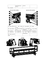
Left side of the machine 


right side of the machine


42

fasten belt roll  43

shut  down 

system 

44

Y axis motor 

45

frame 

46

waste ink box 

47

header air draft 

panel   

48

gas  and  liquid 

detach box 

49

big  junction 

plate 

50

up beam 

51

buffer stick 

52

bistage belt roll  53

x axis motor 

54

hydrate lid 

55

hydrate cap 

56 

up 

beam 

junction plate 

57

vacuum panel 

58

small  junction 

plate 


Carriage   


Back of the machine 


Содержание KM1024

Страница 1: ...1 Printer KONICA KM256 512 1024...

Страница 2: ...e responsibility If contents and the product parameter of this manual have been already changed we will not notice you The Printer company has no responsibility for technique edit bug and negligence a...

Страница 3: ...2 2 1 Working area 5 2 2 2 Environmental requirements 5 2 2 3 Floor requirements 5 2 2 4 Load bearing requirements 6 2 2 5 Requirements for space reservations 6 2 2 6 Safety requirements 6 Fire preve...

Страница 4: ...39 6 2 3 Introduction to the menu 40 6 3 2 1 JOB menu 40 6 2 3 2 setting menu 40 6 2 3 3 Tools menu 41 6 3 Hardware Setting 42 6 4 Calibration 43 7 Show the information of the software version and th...

Страница 5: ...rinter is not running For any of the following situations please turn off the printer and unplug the power cord of machine from the power outlet Thunderstorm The electricity is off during printing 1 3...

Страница 6: ...sure the printer head is in the initial position and make it fixed before moving the printer 1 5 Danger of electric shock There s two power cords on the printer Please unplug these two power cords bef...

Страница 7: ...wiring board inserted row to connect two power cords Only use the power cord supplied with the printer by Printer Do not use damaged power cord Do not use the power cord supplied with other products D...

Страница 8: ...ot shake the ink bottle this will lead to ink leakage The ink bottle need immediately removing cleaning and drying after a period of time usually three months Cleanliness is important when replacing n...

Страница 9: ...away from the joint devices fabric connected machine or other radio frequency interference Floor should be easy cleaning and does not cause dust and static electricity In order to help operators and...

Страница 10: ...storage room and must be made clear identity to meet the professional requirements of safety regulations The storage of ink and solvent must strictly abide by local ink storage use and storage of fue...

Страница 11: ...e 2 2 8 Operator requirements For machines operators following requirements and responsibilities are needed Responsible for operation and maintenance of machine Keep connection with Printer technical...

Страница 12: ...t finish all preparation and cleaning work before the engineer arrives because dust may cause some damage to the machine Customers should prepare other necessary device such as Apple Computer and Phot...

Страница 13: ...must drive smoothly during transportation without brakes sharp turns etc which will result in the beating and rollover of wooden box 2 4 2 unpacking If the box has been damaged before opening took pho...

Страница 14: ...p left baffle 15media up left bracket 16 media up roller 17 down beam 18 rubber feed roller 19 feed roller 20 media pressure 21 air draft 22 pinch roll system 23 fasten shaft 24liner slider 25 raster...

Страница 15: ...shut down system 44 Y axis motor 45 frame 46 waste ink box 47 header air draft panel 48 gas and liquid detach box 49 big junction plate 50 up beam 51 buffer stick 52 bistage belt roll 53 x axis motor...

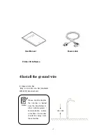
Страница 16: ...re 1 Bury an iron bar Bury a 1m 1 5m iron bar diameter 1CM 2CM into moist soil Notice Please confirm whether the iron bar is buried near the transformer or other national power communication cables or...

Страница 17: ...of the machine the parts without painting such as castor and public wiring board ground 4 Measurement of ground resistance When the machine power on measure the machine phase and the zero line with el...

Страница 18: ...y The install of the ground wire connect the ground wire to the public ground junction plate use the multimeter to the AC 200 V switch black pen to the ground wire red pen to the input zero wire the n...

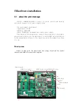
Страница 19: ...15 To pump CN8 Ymotor USB2 0 to computer KM256 carriage board Sub ink tank senor Raster encoder LcLmYMCK power 24v...

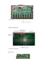
Страница 20: ...16 To main board To KM256 print heads KM512 carriage board Sub ink tank senor Raster encoder LcLmYMCK power 24v To main board To KM512 print heads carriage board to the print heads KM512 1024...

Страница 21: ...17...

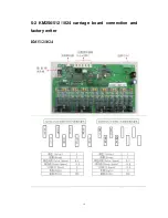
Страница 22: ...18 5 2 KM256 512 1024 carriage board connection and factory writer KM512 1024...

Страница 23: ...19...

Страница 24: ...20 KM256...

Страница 25: ...21 5 3 power outlet Main power Heater power Main power outlet Heater power outlet vacuum...


Страница 26: ...of cleaner suck inlet solid Consist of cleaner suck inlet solid state relay the vacuum power outlet state relay the vacuum power outlet state relay the vacuum power outlet state relay the vacuum power...

Страница 27: ...in 4 absorb the cleaner with injection Note Please clean the capping every week please clean the vicinity of the capping everyday when it does not work please add Insurance film to avoid the dust Firs...

Страница 28: ...the button the capping will stop immediately 2 When the capping descend the bottom the buzzer on the panel will alarm the capping will automatically stop to descend 3 The capping in the bottom will au...

Страница 29: ...he heating control panel front heater bed heater rear heater and print head heater Mode light under working will continue to display four different modes 1 2 3 4 Press mode button into the setting sta...

Страница 30: ...heating mode and exit setting mode Setting case 1 Set the temperature at 35 to heat the platform 2 Off the heating system 3 Open the before heating system at the temperature 40 then set the temperatur...

Страница 31: ...e button is showing in the picture If need to open the left platform to make infrared heating press the left button then will adjust the temperature through spinning the infrared heating screw As for...

Страница 32: ...on switch When the media is installed and start to print please open the two section switch to 0 please open the three section switch to After printed cut the media If need to collect the media please...

Страница 33: ...ntain media through motor reserve Open the collection button to it will loosen the collecting media to process in the later period Media installation H and C machine C12 C8 H8 penetration type feeding...

Страница 34: ...edia Double feeding bar Media installation E and S machine S16 E12 penetration type feeding structure 1 S16 E12 penetration type feeding structure 2 Printing platform Printing platform This structure...

Страница 35: ...31 S16 E12 straight pull feeding structure S16 E12 Placed type feeding structure This structure for frivolous media This structure for normal media...

Страница 36: ...re for almost normal media Show how installation E Series and S series machine S16 E12 penetration type feeding structure 1 S16 E12 penetration type feeding structure 2 This structure for all media an...

Страница 37: ...5 8 Automatical pinch roller S16 E12 straight pull feeding structure S16 E12 Placed type feeding structure This structure for frivolous media This structure is for normal media Automatical pinch roll...

Страница 38: ...wo button can control it As showing in the picture is the front control panel of the machine press the button for two seconds then loosen it the pinch roller will run press the button again for two se...

Страница 39: ...llowing measures The function of the platform suction is to make the media attaching on the platform when printing in order to protect the media from corrugation and raising As showing in the picture...

Страница 40: ...oftware need the system to install Dotnetfx 1 1 or above the version In the installation process to install this software automatically 5 when the software was installed set the hard ware otherwise th...

Страница 41: ...2 Color Space 5 0 5 0 Group Space 2 5 Color Space 2 5 Width 330 Width 330 Head Konica_KM_256_M Head Konica_KM_256_L KONICA512 14PL machine 4 print heads KONICA512 42PL machine 8 print heads Color 4 C...

Страница 42: ...toolbar can execute order of the software The toolbar is showing in the picture The button s mean from left to right successively is Add print job delete print suspend stop nozzle check clean carriag...

Страница 43: ...n print 360 720DPI and 720 720DPI can choose 4 8PASS when print 360 540DPI 720 540 can choose3 6 12PASS when print 360 1080DPI 720 1080DPI can choose 6 12PASS when print 360 1440DPI can choose 8 PASS...

Страница 44: ...perate opening file put the file into job area 6 2 3 2 setting menu Setting menu include the order such as save upload storage setting into KONICA upload setting from KONICA and compile 1 save upload...

Страница 45: ...ng 50 PASS fill in 50 in the Auto clean and fill in 3 in the cleaning times Idle spray is to spray when the machine in spare and this option must choose 3 Color bar Setting to the color bar The space...

Страница 46: ...according to the print head After inputting the voltage click apply to main board Please don t correct voltage casually 6 3 Hardware Setting The hardware setting provided the flexible system use you c...

Страница 47: ...Step six Group Select printer head group number 2 3 4 Step seven Width Select printer width 1 8m 2 5m 3 2m 3 3m The color spacing and the group spacing can act according to the color and the group nu...

Страница 48: ...ime is longer setting cleaning times according to the nozzle broken status Then perform automatic cleaning button Step three Setting print origin Click the move button Move carriage to the propriety p...

Страница 49: ...45 Angle Check check the printed pattern see figure OK The first group head The second group head NG The print head installment does not have level needs to do the physical position adjustment...

Страница 50: ...igure OK The first group head The second group head NG The print head installment not verticality need to do the physical position adjustment M of the first group and M of the second group appear over...

Страница 51: ...original foundation Duplication this step is most uneven until 0 position arrangement Click next the horizontal right calibration perform print check the pattern take M as an example see figure This p...

Страница 52: ...most uneven The choice pattern to the uneven position and input correspondence numeral the method is adds together in the original foundation Duplication this step is most uneven until 0 position arr...

Страница 53: ...rinting the machine will spare on the origin position Printing While printing the job is not disturbed by stop and pause or cleaning Pause The printing job is paused stop The printing job is stoped Cl...

Страница 54: ...will print with the sets if else it will control by the software Pass setting Pass list 1 12 If the pass set is wrong and the choose pass is 4 the job will print in 4 pass Speed If the file sets is wr...

Страница 55: ...51 7 7 7 7 2 2 2 2 3 Calibration parameter 3 Calibration parameter 3 Calibration parameter 3 Calibration parameter 7 7 7 7 2 2 2 2 4 Preference set 4 Preference set 4 Preference set 4 Preference set...

Страница 56: ...y maintain the machine in accordance with the guidance in this chapter for regular equipment maintenance and testing or it will cause the unknown damage Warning Do not turn off the machine before take...

Страница 57: ...the coupling top wire clean the dust in machine body Check the PC and Virus user 4 Quarterly inspection and maintenance Clean the ink system change the ink theca check the infrared heating check the p...

Страница 58: ...est button in standby state Clean the head Click the clean button in standby state 8 2 2 Print test sample to check whether it needs further calibration Under normal working state of machine heating p...

Страница 59: ...damage Check the circuit on the board weather have dust or ink cause long time use will happen short circuit Replace print head Some dust or ink stay on the board can clean with alcohol One head come...

Страница 60: ...the raster encoder Replace it Power supply breakdown Check the 12v 24v voltage of the carriage board Repair it 12V 11 75V 12 25 V 24V 23 2V 25V Carriage board broken Replace it Main board broken Repl...

Страница 61: ...ason Check method solution notice The photoelectric find no media Replace it No feeding The feeding motor damage or wire loosen Replace or reinstall Don t put the fabric correctly Check the fabric edg...

Страница 62: ...oard to the motherboard 40P pin is bad or damaged 4 Please check the signal line of the Y motor drive is correct to access or not 5 Please check the Y motor drive signal wire is broken or not 6 Please...

Страница 63: ...damaged 6 Please check the interface board ink supply chip is damaged or not Normal boot flash jet after working for a period of time back to the original logic does not flash jet a painting can be a...

Страница 64: ...or damaged 7 please check the interface board DB15 signal to the servo controller signal line if there were bad and damage phenomena horizontal for AC motor 8 please check the USB data lines are inta...

Страница 65: ...without action 1 please use the independent 5V 6A power to the motherboard and the use of high quality and stable power supply 2 please check whether the normal voltage current environment Boot reset...

Страница 66: ...d factory number of the machine which can be found on its body tag If the LCD control panel displays an error code please write down the code and refer to the error codes the computer you are using an...

Страница 67: ...sor measurement error 1 examination paper width sensor connected whether normal 2 replacement test paper width sensor 400100F9 COM Command_Abort_Pa per JamX Horizontal cardboard 1 reinstall the paper...

Страница 68: ...Board_Pause_UART 1_TXTIMEOUT Sports COM timeout 20020003 Core Board_Pause_UART 2_TXTIMEOUT Main board com overtime 80020000 Core Board_Service_SX2 In the USB chip service error 02020002 Core Board_Upd...

Страница 69: ...password failed 1check the pass word 2 reset the pass word 3 replace the main board UI Error_Update Fail Upgrade failed 1 check up data file 2 up date again 3 replace main board Up date Display_Faile...

Отзывы: