E-7
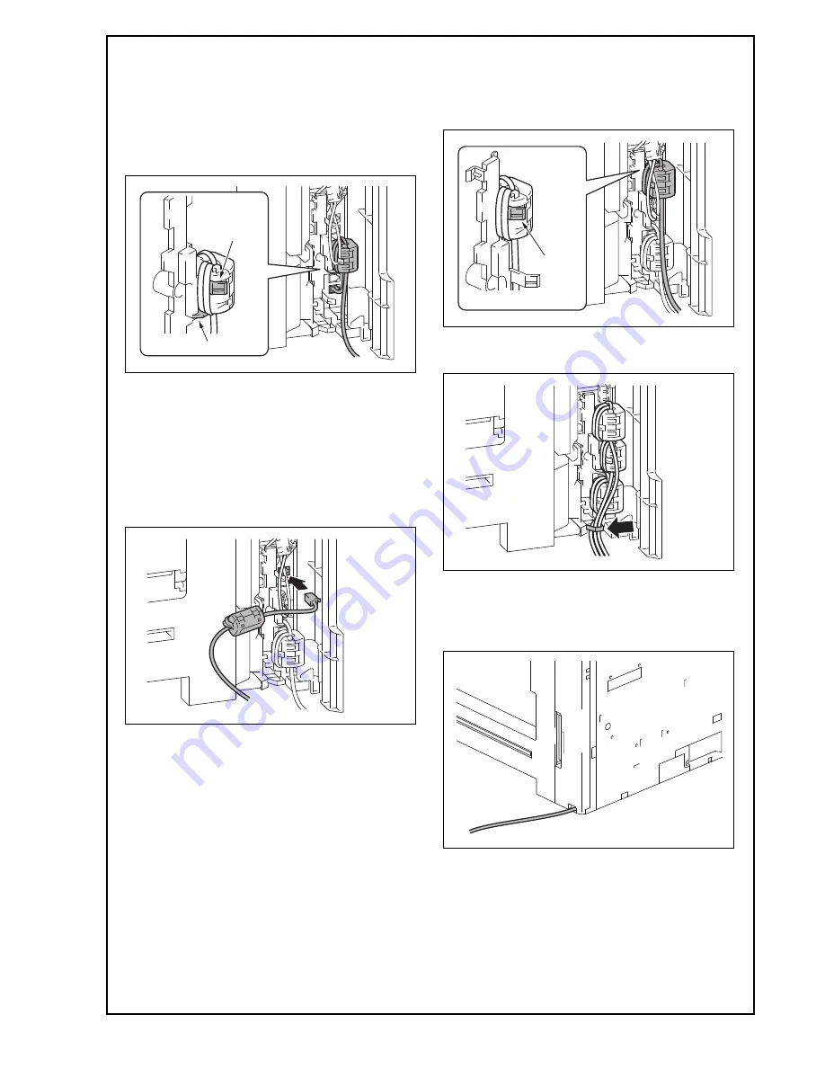
c) House the ferrite core of the modular cable in
the machine.
Note:
• Pass the protrusion shown in the illustration
below through the cable wound around the fer-
rite core in step a).
• Position the ferrite core so that it is placed on
the base shown in the illustration below.
<Only when adding LINE-2>
(4) Perform the following steps.
a) Connect the supplied modular cable in the
modular jack (LINE) of the fax kit (Line 2).
Note:
If the user is connected with a key telephone sys-
tem or a private branch exchange (PBX), do not
connect the modular cable to where other than an
analog line.
b) House the ferrite core of the modular cable in
the machine.
Note:
Pass the cable wound around the ferrite core
through the protrusion.
(5) Route the modular cable through the harness
guide.
<When adding no paper feed options/desk or when
using the Desk DK-705>
(6) Pass the modular cable into the hole in the lower
portion of the rear right cover.
Base
Protrusion
Protrusion


