E-4
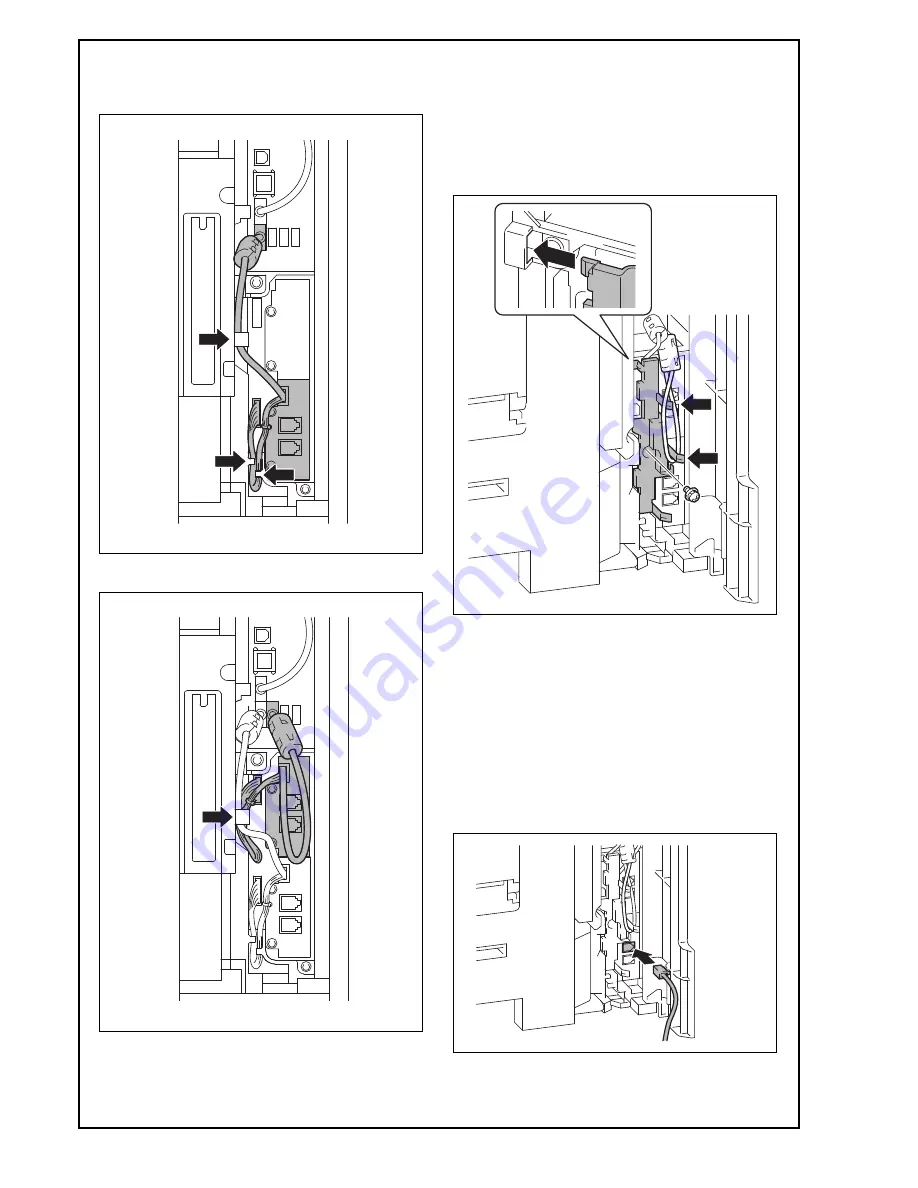
(10) Route the fax kit harness and the USB cable as
shown in the illustration below.
<Line 1>
<Line 2>
(11) Reinstall the connector cover that has been
removed in step (3).(One screw)
Note:
• Fit the connector cover protrusion in the portion
of the machine shown in the illustration below.
• Be careful not to pinch the harness.
• Wind the USB cable of the Line 2 around the
two protrusions as shown in the illustration.
<Routing of the modular cable>
a. When the ferrite core is not installed to the
supplied modular cable
(1) Insert the supplied modular cable in the modular
jack (LINE).
Note:
If the user is connected with a key telephone sys-
tem or a private branch exchange (PBX), do not
connect the modular cable to where other than an
analog line.


