background image

7. Jam display

Field Service Ver. 1.0 Jun. 2008

DF-612/SP-503/MS-501

T

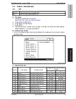
roubleshooting

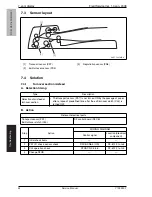
7.3

Sensor layout

7.4

Solution

7.4.1

Turnover section misfeed

A. Detection timing

B. Action

[1]

Transport sensor (PS7)

[3]

Registration sensor (PS8)

[2]

Exit/turnover sensor (PS9)

A0EYF4C501DA

[2]

[3]

[1]

Type

Description

Detection of misfeed at 
turnover section

• The transport sensor (PS7) is not turned ON by the passage of paper 

after a lapse of predefined time after the exit/turnover clutch (CL3) is 
turned OFF.

Relevant electrical parts

Transport sensor (PS7)

Exit/turnover clutch (CL3)

DF control board (DFCB)

Step

Action

WIRING DIAGRAM

Control signal

Location (Electrical 

component)

1

Initial check items

2

PS7 I/O check, sensor check

DFCB CN6-3 (ON)

DF-612 F to G-6

3

CL3 operation check

DFCB CN2-5 to 6

DF-612 F to G-2

4

Change DFCB

44


          Service Manual                                                          Y109

850

-

7

Содержание DF-612

Страница 1: ...DF 612 SP 503 MS 501 Option Printer SERVICE MANUAL Code Y109850 7...

Страница 2: ...PUBLICATION ISSUED BY Olivetti S p A 77 Via Jervis 10015 Ivrea TO Italy Copyright 2008 Olivetti All rights reserved...

Страница 3: ...ft margin of the revised section The number inside represents the number of times the revision has been made To indicate clearly a page that contains the revision is shown near the page number of the...

Страница 4: ...y parts list 11 3 2 2 Cleaning parts list 11 3 3 Disassembly Assembly procedure 12 3 3 1 Front cover 12 3 3 2 Rear cover Rear left cover Rear lower cover 13 3 3 3 Document feed tray rear cover 14 3 3...

Страница 5: ...sure Width 37 5 2 5 Paper Passage 38 5 3 Sensor Check Scan 39 5 3 1 ADF 39 6 Mechanical adjustment 40 6 1 Adjusting skew feed 40 Troubleshooting 7 Jam display 43 7 1 Initial check items 43 7 2 Misfeed...

Страница 6: ...1 sided mode 20 pages min 2 sided mode 10 pages min Color scan 300 dpi 1 sided mode 20 pages min 2 sided mode 10 pages min Monochrome scan 300 dpi 1 sided mode 40 pages min 2 sided mode 20 pages min T...

Страница 7: ...ets severely curled 15 mm or more Sheets misfed due to being dog eared or fed in askew OHP film Transparency film Paper feed failure transport failure Label paper Paper feed failure transport failure...

Страница 8: ...A4S x x x x OK OK A5 x x x x OK OK 182 mm B5S x x x x x x OK 148 mm A5S x x x x x x x OK Max original size 11 8 1 2 5 1 2 Mixed original size 11 x 17 8 1 2 x 11 8 1 2 x 14 8 1 2 x 11S 5 1 2 x 8 1 2 5...

Страница 9: ...1 Product specification Field Service Ver 1 0 Jun 2008 DF 612 SP 503 MS 501 Outline Blank Page 4 Service Manual Y109850 7...

Страница 10: ...intenance represents the isopropyl alcohol 2 1 1 Separation roller A Periodically cleaning parts cycle Separation roller Every 30 000 originals feed B Periodically replaced parts cycle Separation roll...

Страница 11: ...501 Maintenance D Replacing procedure 1 Pull the lever 1 to open the feed cover 2 2 Raise the knob 3 and open the doc ument guide 4 3 Unhook the tab 1 and remove the two arms 2 4 Open the frame 3 A0EY...

Страница 12: ...Jun 2008 2 Periodical check DF 612 SP 503 MS 501 Maintenance 5 Remove two screws 1 and the plate 2 6 Remove two springs 3 two bearing splits 4 and the separator roller 5 A0EYF2C003DA 1 2 3 3 5 4 Y1098...

Страница 13: ...eriodically cleaning parts cycle Feed roller Every 30 000 originals feed Pick up roller Every 30 000 originals feed B Cleaning procedure 1 Open the feed cover 1 2 Using a cleaning pad dampened with al...

Страница 14: ...xit rollers Every 30 000 originals feed B Cleaning procedure 1 Open the feed cover 1 2 Using a cleaning pad dampened with alcohol wipe three regist rollers 1 and three rolls 2 clean of dirt 3 Lift up...

Страница 15: ...prevent them from being removed by mistake Do not remove or loosen any of the red painted screws in the field It should also be noted that when two or more screws are used for a single part only one r...

Страница 16: ...r P 14 4 Units Auto document feeder unit P 15 5 Document feed tray P 16 6 ADF scanner assy P 17 7 Rollers Feed roller Pick up roller P 19 8 Transport roller 1 2 P 23 9 PWBs DF control board DFCB P 24...

Страница 17: ...3 Disassembly Assembly procedure 3 3 1 Front cover 1 Open the auto document feeder unit 2 Remove three screws 1 3 Close the auto document feeder unit 4 Open the feed cover 1 5 Remove the rubber cover...

Страница 18: ...Remove the screw 1 7 Push to remove the three tabs 2 and then remove the front cover 3 3 3 2 Rear cover Rear left cover Rear lower cover 1 Open the feed cover 1 2 Lift up the document feed tray 1 A0E...

Страница 19: ...e rear cover 2 rear left cover 3 4 Remove three screws 1 and remove the rear lower cover 2 3 3 3 Document feed tray rear cover 1 Lift up the document feed tray 2 Remove five screws 1 and remove docume...

Страница 20: ...Remove the screw 1 and remove the cover 2 4 Remove the screw 1 and remove the ground terminal 2 5 Disconnect the connector 3 NOTE When disconnecting the connector 3 use care not to allow the flat cab...

Страница 21: ...document feeder unit 2 3 3 5 Document feed tray 1 Remove the front cover See P 12 2 Remove the rear cover rear left cover See P 13 3 Remove the screw 1 and remove the cover blind front 2 4 Remove the...

Страница 22: ...r rear lower cover See P 13 3 Remove the document feed tray See P 16 4 Remove the cooling fan See P 27 5 Remove the screw 1 and remove the cover blind rear 2 6 Disconnect all connectors but CN1 from t...

Страница 23: ...d the bracket support 2 9 Remove three shoulder screws 1 three screws 2 and the ADF scanner assy 3 NOTE At reinstallation note that the screw 2 M3x14 at the position indicated by the arrow differs fro...

Страница 24: ...P 503 MS 501 Maintenance 3 3 7 Feed roller pick up roller 1 Open the feed cover 1 2 Remove two screws 1 3 Unhook two tabs 2 remove the feed cover 3 4 Unhook the spring 1 A0EYF2C500DA 1 A0EYF2C017DA 1...

Страница 25: ...501 Maintenance 5 Unhook two tabs 1 and remove two lock levers 2 6 Remove the knob 3 7 Remove the screw 1 and remove the sensor holder 2 8 Snap off the E ring 1 at the front A0EYF2C019DA 1 2 2 3 A0EY...

Страница 26: ...he E ring 1 in the rear 10 Disconnect the connector 2 remove the clutch 3 and gear 4 11 Remove the screw 1 and remove the ground terminal 2 12 Snap off the E ring 1 and remove the bushing 2 at the rea...

Страница 27: ...ing 1 14 Slide the shaft 1 toward the rear and then slide it to the front Then remove the feed roller pick up roller assy 2 from the frame top 15 Snap off the E ring 1 and remove the bushing 2 and fee...

Страница 28: ...erring to the illustration shown below perform the disassembly procedure to remove the transport roller 1 3 and transport roller 2 4 NOTE Be sure to replace the transport roller 1 3 and transport roll...

Страница 29: ...the rear cover See P 13 2 Disconnect ten connectors 3 Remove four screws 1 and remove the DF control board 2 3 3 10 Print lamp board PLB 1 Remove the front cover See P 12 2 Disconnect the connector 1...

Страница 30: ...sconnect the connector 2 and remove the take up motor assy 3 3 Remove two screws 1 and remove the take up motor 2 3 3 12 Transport motor M2 1 Remove the front cover See P 12 2 Disconnect the connector...

Страница 31: ...SP 503 MS 501 Maintenance 3 Disconnect the connector 1 4 Remove two screws 1 and remove the transport motor assy 2 5 Remove two screws 1 and remove the transport motor 2 A0EYF2C035DA 1 A0EYF2C036DA 1...

Страница 32: ...ar left cover rear lower cover See P 13 2 Disconnect the connector CN10 1 of the DF control board 3 Remove the harness from three wire saddles 1 4 Remove the screw 1 and remove the ground terminal 5 R...

Страница 33: ...r unit NOTE Use care not to dirty the document pad 1 that has been peeled off from the feeder unit NOTE When reinstalling the document pad 1 place it on the original glass leaving an edge margin of 1m...

Страница 34: ...4 Remove the screw 1 disconnect the hookup connector 2 and remove the stamp unit 3 3 3 15 Spare TX Marker Stamp 2 1 Pull the lever 1 to open the feed cover 2 2 Raise the knob 3 and open the doc ument...

Страница 35: ...e cleaning procedure of maintenance represents the isopropyl alcohol 3 4 1 White sheet 1 Open the auto document feeder unit 2 Clean the white sheet 1 3 4 2 Registration sensor 1 Open the auto document...

Страница 36: ...r 1 0 Jun 2008 3 Other DF 612 SP 503 MS 501 Maintenance 3 4 3 Black sheet ADF glass assy 1 Open the auto document feeder unit 2 Clean the black sheet 2 with the cleaner 1 A0EYF2C513DA 1 2 Y109850 7 Se...

Страница 37: ...3 Other Field Service Ver 1 0 Jun 2008 DF 612 SP 503 MS 501 Maintenance Blank Page 32 Service Manual Y109850 7...

Страница 38: ...nlight ventilation etc levelness of the installation site The original has a problem that may cause a defective image The density is properly selected The original glass slit glass or related part is...

Страница 39: ...k that the lengths of the refer ence lines reproduced on the copy A Main scan direction and B Sub scan direction meet the following specifications 6 If the reference line lengths A and B are not withi...

Страница 40: ...ifications 14 Touch OK on the Service Mode screen 15 Turn OFF the main power switch then wait for 10 sec or more and turn ON the main power switch 5 2 2 Feed 1 Load the test chart 1 in the ADF 2 Call...

Страница 41: ...ce in the width falls within the specified range 6 If the difference in the width of a falls outside the specified range make the following adjustment 7 Touch OK 8 Touch ADF Adjustment o Feed 9 Touch...

Страница 42: ...he clear key and change the setting value using the 10 key pad Press the key to change the code 7 Touch OK 8 Press the Reset key 9 Touch OK on the Service Mode screen 10 Turn OFF the main power switch...

Страница 43: ...2 Sided 6 Set the original in the feed tray 7 The Start key color changes from orange to blue 8 Press the Start key The operation starts NOTE After starting the operation by pressing the Start key if...

Страница 44: ...misfeed occurs A0EYF3E512DA Symbol Panel display Part Signal name Operation characteristics panel display 1 0 PS1 Empty Document empty sensor Paper present Paper not present PS2 Width Sensor 1 Documen...

Страница 45: ...mes repeatedly in single side mode 4 Fold all 5 sample copies as illus trated and check for any deviation Deviation on the sample will be Y 5 Obtain the difference between the deviation of the chart a...

Страница 46: ...SP 503 MS 501 Adjustment Setting 7 Remove five screws 1 rear cover 2 and rear left cover 3 NOTE When installing the rear cover and rear left cover be sure to place the protective film 1 in the cover A...

Страница 47: ...tomatic docu ment feeder in either direction shown by the arrows and select an appro priate graduation line 1 When the amount of deviation is a positive value move it in the direction A When the amoun...

Страница 48: ...the paper Instruct the user on the correct paper storage proce dures Is a foreign object present along the paper path or is the paper path deformed or worn Clean or change the paper path Are the rolls...

Страница 49: ...turnover section The transport sensor PS7 is not turned ON by the passage of paper after a lapse of predefined time after the exit turnover clutch CL3 is turned OFF Relevant electrical parts Transport...

Страница 50: ...operation check DFCB CN2 1 to 2 DF 612 F to G 1 4 Change DFCB Type Description Detection of misfeed at transport section The registration sensor PS8 is not turned ON by the passage of paper after a la...

Страница 51: ...4 ON DF 612 F to G 5 4 Change DFCB Type Description Short length misfeed The original being fed through the unit has a length shorter than the shortest length of the original supported by the unit Th...

Страница 52: ...UPDATING STATUS DATE UPDATED PAGES PAGES CODE 09 2008 1ST EDITION 52 Y109850 7...

Отзывы: