


32
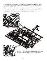
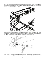
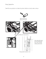
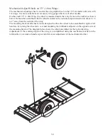
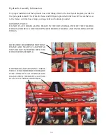
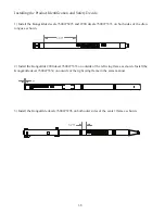
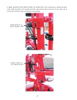
Detail view of front frame
hinge pin with locking clip
pin installed.
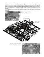
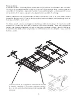
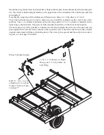
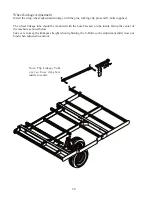
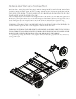
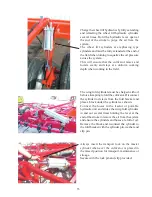
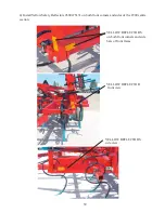
Final Assembly Centre Section and Wings:
Move the wing assemblies into position beside the centre section.
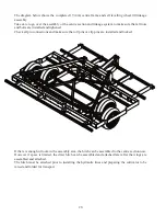
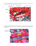
Install the wing hinge pins according to step 1, 2 & 3 in the diagram below. The hinge plate bolts should
be loose to allow easier alignment and insertion of the hinge pins. The main hinge pins are designed to
lock in position and must be turned so that when they are inserted through the hinge plates and centre
frame, the pin stub locks into the second hole in the hinge plate before the washer, castle nut and cotter
pin are be installed.
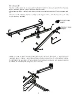
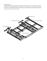
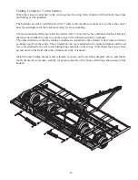
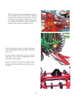
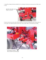
The front toolbar also acts as a 3rd hinge to provide greater stability for the front frame extension. Secure
the front toolbar hinge pins in place with the locking clip pin. When the pins are installed tighten the
hinge plate bolts
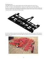
1
2
3
Содержание VIBRO TILL 2900 Series
Страница 44: ...44 660 005 033 February 2016...


