Kongsberg SIMRAD 11252236 Скачать руководство пользователя страница 26

Tillerpilots TP10/TP22/TP32

26

E04818  Issue 1.0

6.2  Troubleshooting

These simple checks should be carried out before seeking tech-
nical assistance and may save time and expense. Before con-
tacting your servicing agent, please note the Tillerpilot’s serial
number.

Symptom

When engaged, the pilot 
immediately applies a large 
helm angle and increases 
course error.

After functioning normally 
course is suddenly lost and the 
Tillerpilot goes into Standby 
Mode.

Helm is hard over and alarm is 
continuously on.

Power socket is live, but pilot 
is not on.

Loss of course under Steer To 
Wind Mode.

Cannot select Steer To Wind 
Mode.

Cannot select Nav Mode.

Autotack function not 
working.

Pilot exits Nav Mode before 
waypoint is reached.

Pilot does not hold accurate 
course in Auto Mode.

Probable Cause

•Tillerpilot is configured for Port 
   hand setting but installed on 
   Starboard side (or vice versa).

• Power interrupted briefly, or low 
   voltage. 
• Cable used to socket too small.  
• Intermittent connection.

• Steerage way insufficient to control 
   course, or sails are aback.  Pulsing is 
   a correct safety feature when tiller is 
   at full travel.

• Socket is wired incorrectly.

• Apparent wind has become too light 
   to give a consistent direction.

• Masthead unit is not connected. 
• SimNet system is not switched on
   or powered.  
• Required NMEA sentence not being  
   transmitted.

• GPS/Chart Plotter not connected.  
• Waypoint not active.
• Wrong NMEA format is being used.

• Pilot is in Nav Mode.  
• Pilot is in Steer To Wind Mode and
     a) apparent wind is >90º
     b) autotack being attempted is in 
         the wrong direction.

• Cross Track Error has exceeded 1.2 
   Nm.

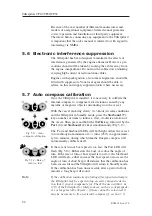
• Fluxgate compass is being affected
   by interference from nearby 
   magnetic influences (binnacle
   compass, speakers) or metallic
   objects (winches, deck hardware etc).

Remedy

•  Refer to section 4.1.

•  Increase size of cable.  
•  Check all connections.  
•  Charge batteries.  
•  Uprate batteries.

• Reset the vessel on course
   and re-engage pilot

• Check wiring of socket 
   (section 5.2).

• Change to Compass 
    Mode.

• Check connections.
• Check system is on.

• See section 6.3 & check 
   NMEA connections.  

• Check connections.
• Activate waypoint/route.
• Check NMEA0183 format 
   is being transmitted by 
   navigational receiver.

•  Exit Nav Mode.  
•  Luff up until apparent 
    wind is less than 90º.

•  Reset the vessel on course 
and re-engage Nav Mode.

• Check compass has been
   calibrated (section 5.6).
• Fit external SimNet
   compass.
• Replace binnacle compass
   with bulkhead compass.
• Relocate objects that are
   causing interference.

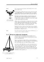
Содержание SIMRAD 11252236

Страница 1: ...M A X I M I Z I N G Y O U R P E R F O R M A N C E A T S E A...

Страница 2: ......

Страница 3: ...Instruction Manual III E04818 Issue 1 0 Simrad TillerPilotsTM TP10 TP22 TP32 Tillerpilots M A N U A L...

Страница 4: ...our policy of continual development and improvement No part of this publication may be reproduced stored in a retrieval system or transmitted in any form electronic or other wise without prior permis...

Страница 5: ...bration mode 14 4 3 Adjusting Gain 15 4 4 Adjusting Seastate 15 4 5 Autotrim 16 5 INSTALLATION 5 1 Fitting the Tillerpilot 17 5 2 Electrical installation 19 5 2 1 Installing the TP22 and TP32 19 5 2 2...

Страница 6: ......

Страница 7: ...to operate the Tillerpilots remotely using the HR22 Hand Remote For more details please refer to the sepa rate instruction sheet supplied with the HR22 To ensure the best results from your Tillerpilot...

Страница 8: ...t wind angle data from the wind transducer for Steer To Wind mode boat speed data from the Speed instru ment and heading data from the compass transducer Additionally heading data from the Tillerpilot...

Страница 9: ...pplicable 2 2 Autopilot mode While in Standby mode the pushrod can be manually driven in and out by pressing the arrowed Port and Starboard keys which allows power steering of the vessel To engage Aut...

Страница 10: ...k Fig 2 4 The operation of the Tillerpilot will differ during an autotack depending on whether the pilot is in Steer To Compass or Steer To Wind mode 2 4 1 Autotacking in Compass mode If in Compass mo...

Страница 11: ...ot will be steering directly to a waypoint the autotack facility is disabled while in Nav mode If it is necessary to perform an autotack disengage Nav mode by pressing the NAV key then perform the aut...

Страница 12: ...ext to the NAV key will light and the Tillerpilot will steer to the first waypoint using Cross Track Error and Bearing To Waypoint information from the navigational receiver to main tain an accurate c...

Страница 13: ...angle on the opposite tack As a safety feature autotack is disabled when sailing downwind Note Nav mode cannot be selected while in Steer To Wind mode to activate return to Compass mode first 3 3 Usi...

Страница 14: ...the TACK key then press NAV CAL Fig 4 3 The Starboard LED will illuminate to indicate that Gain adjustment is selected To toggle between Gain and Seastate adjustment press TACK the Port LED will illum...

Страница 15: ...ates the level of the Gain setting Use the Port and Starboard keys to adjust the Gain setting between 1 and 9 Fig 4 5 Press NAV CAL to confirm settings and return to normal operation or press TACK to...

Страница 16: ...elm varies according to factors such as strength of wind boat speed sail trim and amount of sail set If no account of these were taken then the vessel would tend to veer off course or pull around head...

Страница 17: ...e Horizontal 38mm With the tiller amidships and the pushrod in the midstroke posi tion the Tillerpilot should be exactly 90 to the tiller Fig 5 2 Fig 5 1 Installation cross section NAV STBY TACK STBY...

Страница 18: ...and stowed easily To fit the tillerpin drill a 6 3 mm 0 25 in hole in the tiller ensure that this is on the centerline of the tiller and is vertical Drill to a depth that allows only the top 18 mm 0...

Страница 19: ...between the inter faced equipment which would render the equipment inoper ative Mount the bulkhead socket on a vertical surface to prevent stand ing water gathering around or in the socket Always fit...

Страница 20: ...d TP32 Tillerpilots are linked to other SimNet compatible equipment via the integral SimNet cable and plug in the bulkhead socket All SimNet units Instruments Chartplotters Radars Auto pilots etc use...

Страница 21: ...d to the SimNet bus and will automatically detect the nav and instrument data sources with no user intervention necessary If the SimNet bus includes more than one data source the Tillerpilot will use...

Страница 22: ...t turn off the Tillerpilot To select StandAlone mode press and hold the TACK and keys and turn the power on Fig 5 10 To select System mode press and hold the TACK and keys and turn the power on Fig 5...

Страница 23: ...beled DATA and COMMON or COM These should be connected to the Tillerpilot s NMEA cable as follows Fig 5 12 NMEA integration examples NMEA0183 Speed Wind or SimNet Tillerpilot power GPS Chartplotter No...

Страница 24: ...llerpilot in Standby mode press the Starboard key a number of times to induce a slow clockwise rotation of the vessel Then press and hold the TACK key followed by the Port and Starboard keys simultane...

Страница 25: ...hauled to set a course a few degrees free of that normally sailed under manual control to avoid luffing into the wind 3 When running dead downwind a human pilot can see visual signs warning him if th...

Страница 26: ...Socket is wired incorrectly Apparent wind has become too light to give a consistent direction Masthead unit is not connected SimNet system is not switched on or powered Required NMEA sentence not bei...

Страница 27: ...waypoint great circle VHW Boat Speed XTE Cross Track Error Note The Cross Track Error XTE information has a maximum value of 1 2 Nautical Miles If the XTE exceeds this while using Nav mode the Tiller...

Страница 28: ...0 PRE150 PRE300 Part No Length 30mm 1 18 60mm 2 36 90mm 3 54 120mm 4 72 150mm 5 90 300mm 11 81 TB30 TB60 TB90 TB120 Part No Height 30mm 1 18 60mm 2 36 90mm 3 54 120mm 4 72 Length PB30 PB60 PB90 CB1 13...

Страница 29: ...Drive System TP10 Screw thread TP22 Screw thread TP32 Recirculating ballscrew Operating Stroke 250 mm 10 in Peak Thrust TP10 65 kg 143 lbs TP22 70 kg 154 lbs TP32 85 kg 187 lbs Hardover time 0 kg TP1...

Страница 30: ...prepaid to the agent in the country of purchase with a copy of the receipted invoice showing the date of purchase Where possible return all the components unless you are certain that you have located...

Страница 31: ......

Страница 32: ...M A X I M I Z I N G Y O U R P E R F O R M A N C E A T S E A...

Отзывы: