Kondo 2500 Series Скачать руководство пользователя страница 12

12

■Controlling Servos with a Control Board
 Only one servo per output port may be connected when using a PWM 
 signal. Uncheck the  Serial Signal  check box. 

■Control Using Programming
 Please refer to  When using a PWM signal  in the ICS 3.5 Command 
 Reference to control the servos in PWM mode.

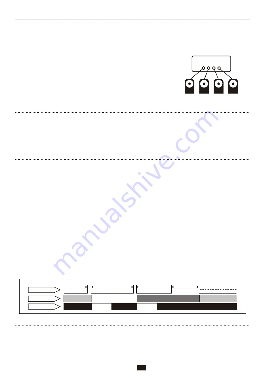
Example of how servos are 

connected in PWM control 

mode.

Control Board

Servos

1  2  3‥n  

1    2    3    n

 (Ch)

※Voltage drops and/or noise in the signal may cause unintentional movement during operation. Use this 

product with caution. 

※Using the position capture (teaching) function in conjunction with a home-made control board requires 

pull-up resistor  in the signal wire from the control board CPU. Furthermore, the CPU servo control board 

needs to be able to change between signal input and output. Kondo control boards are compatible with the 
position capture function.

Points of Caution When Using a PWM Signal

Using a PWM Signal

100〜200μsec

50μsec

700〜2300μsec

■ Diagram showing the timing of the signal and servo movement ■

■Position Command (MOVE)

The output shaft of the servo rotates in accor-
dance with the PWM input signal.
700μs (-135 ° ) to 1500μs (0 ° ) to 2300μs 
(+135°)

■Power Limitation 

Inputting a pulse width of 50μs will reduce the 
power output of the servos. This state of limited 
power output will be maintained until the servos 
receive the next position command with a pulse 
width between 700μs and 2300μs.

■Characteristic Change (Stretch preset change)

Inputting a pulse width of 100μs, 150μs or 200μ
s will instruct the servos to change between three 
preset characteristics (SET1 ˜ SET3 stretch set-
tings) saved within the servo.
The servos will maintain the state the output shaft 

was in directly before they were instructed to 
change position.

Preset parameters (SET1, SET2 and SET3) can be 
changed using the ICS menu. Setting 1 (SET1) will 
automatically be selected when turning the servo 
power on. 。

Stretch 1 (SET1) 100μs +/-10μs
Stretch 2 (SET2) 150μs +/-10μs
Stretch 3 (SET3) 200μs +/-10μs

■Position Capture (Teaching)

Inputting a pulse width of between 50μs and 200
μs will instruct the servos to output a pulse width 
that indicates the current position of the servo 
output shaft. This pulse output from the servos is 
then read by the control board and the current posi-
tion of the servos can be ascertained.

Movement of Servos Using a PWM Signal

RCB-3HV

RCB-3J

PWM Compatible Control Boards

When operating this product using a PWM signal, position commands 
can be made using general radio control signals. 
Functionality can also be expanded by using other specific signals.

     PWM cycle compatibility:3ms 〜 30ms

Pulse width: Normal operation 700μs to  2300μs. 
        Expanded function 50μs to 200μs.

※The KRS 3000 series is designed to be operated between 6.0 and 7.4 volts. Ensure the input current is within that range.

KCB-5   : 6 x PWM outputs. Teaching and characteristic  change are possible depending on the programming. 
               (Cannot be used in conjunction with serial terminal, so separate wiring is required.)

: RCB-3HV/RCB-3J: 24 x PWM outputs. Up to 24 servos can be connected. Suitable for teaching  

  and changing characteristics. 

Normal movement

Normal movement

Servo movement 

input

 signal

Hold

Input

Input

Input

Servo signal line

Output

Output

Input signal present
No input signal present

Power limitation

Содержание 2500 Series

Страница 1: ...e department with your inquiry Please note that we are cannot answer questions on control programming Thank you for your understanding Check the input signal and source voltage before operating this product Pay attention to the orientation of the connectors and ensure they are correctly plugged in Do not use this product in a place where there it may get wet Do not dismantle or modify this product...

Страница 2: ...V 4031HV ICS Size L43 W32 H32 5 Operating voltage 9 12V Weight 61 2g 61 4g 61 2g 55 2g Maximum operating angle 270 135 Maximum current 3 1A 11 1V Gear material Aluminum Steel POM Communication standards ICS3 5 Serial PWM Control Boards RCB 4HV KCB 5 RCB 3HV KRS 6003R2HV ICS Size L 51 W32 H39 5 Operating voltage 9 12V Weight 103g Maximum operating angle 270 135 Maximum current 6 1A 11 1V Gear mater...

Страница 3: ...ect one end to the signal terminal of the control board and the other end to the signal terminal of the servo The two signal terminals on the servos are internally connected in parallel so you may connect to either one Please refer to page 6 of this manual if you wish to connect multiple servos using the same terminal in a multi drop arrangement 6100 Series 2500 Series 4000 Series Connecting to a ...

Страница 4: ...n be anchored to home made frames or brackets using up to 8 screws Refer to the table in the diagram below for recommended screw sizes 6000 4000 series When frame thickness is 2mm 1 Remove two screws shown in diagram below 2 Secure upper and lower bracketing using designated screws 2000 3000 series When frame thickness is 1mm 1 Remove screws from servo case 2 Secure servo to frame using screws rem...

Страница 5: ...Bearing for KRS 6100 series Aluminum Servo Horn I cut PCDΦ14 M2 offset 0 No 01158 1 pc No 01159 6 pcs Free Horn for KRS 4024 4031 PCDΦ14 M2 offset 0 No 02075 1 pc No 02076 6 pcs PCDΦ17 M2 6 offset 2 Aluminum Cramp Horn No 01042 1 pc No 01043 6 pcs PCDΦ14 M2 offset 0 Aluminum Low height Servo Horn No 02093 1 pc No 02094 6 pcs PCDΦ12 M2 offset 0 Aluminum Small Diameter Horn No 02079 1 pc No 02080 6 ...

Страница 6: ...ection Cable B 300mm 1 M3 6 Low Head Horn Screw 1 6 pcs set ZH Connection Cable A 300mm 6 ZH Connection Cable B 300mm 6 M3 6 Low Head Horn Screw 6 18 pcs set ZH Connection Cable A 300mm 18 ZH Connection Cable B 300mm 18 M3 6 Low Head Horn Screw 18 1 pc M3 8 Low Head Horn Screw 1 本 6 pcs set M3 8 Low Head Horn Screw 6 本 18 pcs set M3 8 Low Head Horn Screw 18 本 KRS 3204 and 3304 servos are not suita...

Страница 7: ...Φ12 M2 offset 0 No 02157 2 pcs No 02158 12 pcs M2 4 Low Head Screw No 02086 100 pcs Flame t 1mm 2 6 4 Flat Head Tapping Screw No 02164 100 pcs Servo Horn Free Horn Free Horn Screw Free Horn Screw Horn Screw Horn Screw Horn Screw Servo Horn Free Horn Horn Screw M3 8 Low Head Horn Screw M3 8 Low Head Horn Screw Installation of Servo Horns 7 ...

Страница 8: ...he larger the neutral position The smaller the number the narrower the neutral position becomes Setting the dead bandwidth too small can result in slight vibrations jitter Range 0 is the narrowest 10 is the widest Punch You can set the initial response level of the servo motors The higher the number the stronger the initial response to input Range 0 is the lowest 10 is the highest Rotation mode Ro...

Страница 9: ...rotation You can set the maximum range of movement for reverse rotation Value range Minimum 3500 Maximum 7000 Temperature restriction This mode enables a limit to be placed on the electrical current Setting a higher value raises the maximum electrical current threshold If an electrical current greater than the set threshold is detected the limiter will come into effect and restrict the current to t...

Страница 10: ...LV Servo 0 115200 100 60 30 90 100 OFF OFF OFF OFF 0 2 1 25 250 11500 3500 40 40 0 11 3 5 3204 0 115200 127 60 30 127 127 OFF OFF OFF OFF 0 1 1 40 250 11500 3500 75 40 0 20 3 5 3304 0 115200 127 60 30 127 127 OFF OFF OFF OFF 0 1 2 80 250 11500 3500 75 40 0 24 3 6 3304R2 0 115200 90 30 60 127 127 OFF OFF OFF OFF 0 2 1 30 250 11500 3500 10 30 0 18 3 6 3302 3301 HV Servo 0 115200 60 60 30 90 127 OFF ...

Страница 11: ... 4HV 2 x serial outputs Suited for daisy chaining up to 32 servos RCB 3HV Not compatible with daisy chain arrangements 24 x serial output ports designed to each connect to one servo for a total of 24 servos KCB 5 4 x serial outputs Up to 10 servos can be controlled per output Use C language for our KCB series servos to allow for greater flexibility of control Dual USB Adapter HS This accessory all...

Страница 12: ...three preset characteristics SET1 SET3 stretch set tings saved within the servo The servos will maintain the state the output shaft was in directly before they were instructed to change position Preset parameters SET1 SET2 and SET3 can be changed using the ICS menu Setting 1 SET1 will automatically be selected when turning the servo power on Stretch 1 SET1 100μs 10μs Stretch 2 SET2 150μs 10μs Stre...

Страница 13: ...02116 1 pc Dual USB Adapter HS 2 4GHz FHSS Tx Rx set No 03099 1 pc KRC 5FH Bluetooth module No 03062 1 pc KBT 1 for 4000 series No 01223 4 pcs Servo Spacer 4000A for 4000 series No 01197 4 pcs Friction Spacer 4000A for 4000 series No 01204 2 pcs Extension Adapter A for 4000 series No 01195 2 pcs Arm Supporter 4000A for 2500 series No 02052 2 pcs Arm Supporter 2500A No 02025 No 02026 6 pcs Bottom C...

Страница 14: ...n t really a problem when operating using PWM movement Servos move erratically The serial movement baud rate may be unsupported Servos may move erratically when they receive a signal baud rate that is not supported Servos that were assigned the same ID may be connected in a daisy chain Daisy chaining servos assigned the same ID on the same output line will result in problems with the signal and er...

Отзывы: