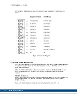
Kollmorgen P5000 Скачать руководство пользователя страница 27

P50330 Installation 


Appendices


       Kollmorgen | April 2013       27


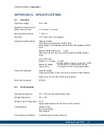
APPENDIX A:  SPECIFICATIONS 

A.1 Electrical 

Input Power Supply 


20-75 VDC 


Rated Drive Output Current  


(Motor Phase Current)   

0 to 2.5 Arms, 3.5 Apeak 

 
Motor Inductance Range 

1 – 50 mH 


Step 

Size 

  1/10

th

 micro-step.  2000 steps/rev. 


Signal Input Characteristics 

Optically isolated.    
Drive steps on leading edge of STEP input.   
Motor rotates in the clockwise direction with 0VDC applied to DIR IN 
input. 
 
Minimum STEP pulse width:    1 µsec 
DIR IN must be true 200 nsec before and after the STEP IN pulse 
edge. 
 
2.5-24 VDC logic 
Minimum “on” voltage:  2.5 VDC. 


           470 Ohm resistor in series required for 12 VDC 

Maximum voltage:  

24 VDC with 1.2 kOhm resistor in series 

Input current:    

4 mA typical at 2.5V, 20 mA typical at 24V. 


Output Characteristics   

Optically isolated.    
Output opens (logic ‘0’) when the drive encounters a fault condition. 


Output current: 5 mA with 1 kOhm pull-up resistor 


Step Pulse Frequency   

200 kHz 


A.2 Environmental 


Operating Temperature 

0ºC - 70ºC (as measured at bottom plate) 

 
Storage Temperature   

0ºC - 70ºC 

 
Maximum Case Temperature 

70°C 
Higher temperatures will reduce the life of the product. 


Cooling 

Method 

  Natural 

cooling 

    Fan-forced 

cooling 


With Heatsink 


Surrounding Air Conditions 

Avoid dust, oily mist and corrosive air 

Содержание P5000

Страница 1: ...stallation Manual Edition B April 2013 Part Number 903 050330 00 Original Document Keep all manuals as a product component during the life span of the product Pass all manuals to future users owners of the product ...

Страница 2: ...film or any other method or stored processed copied or distributed by electronic means without the written permission of Kollmorgen Alerts users to potential physical danger or harm Failure to follow warning notices could result in personal injury or death Directs attention to general precautions which if not followed could result in personal injury and or equipment damage Highlights information c...

Страница 3: ...2 4 5 Mounting Guidelines 12 2 5 WIRING THE P5000 12 2 5 1 Introduction 13 2 5 2 Power Connection 14 2 5 3 Motor Connections 15 2 5 4 Command I O Connections 16 2 5 4 1 Step Drive Mode SW1 ON 17 2 5 4 2 VCO Mode SW1 OFF 19 3 CONFIGURING THE P5000 20 3 1 DIP SWITCH SET UP 20 3 1 1 Operation Mode 20 3 1 2 Standby Current Reduction 21 3 1 3 Resolution 21 3 1 3 1 Input Pulse Resolution 22 3 1 3 2 Velo...

Страница 4: ...clude Current Output from 0 16 2 5 Arms DIP switch selectable 20 75VDC Input Voltage Wave matching for Kollmorgen Motors to provide optimal performance for the Kollmorgen POWERMAX II Hybrid Stepper Motors All Inputs and Outputs are Optically Isolated Command Source from External Step and Direction Inputs or Internal Velocity Controlled Oscillator VCO DIP switch selectable External Single Ended Ste...

Страница 5: ...er System Components and System Diagram The other components that along with the drive comprise a motor control system are Indexer or pulse generator Single power supply 20 75 volts Motor Installation guidelines for these components are described in Chapter 2 Installing the P5000 Stepper Motor Drive ...

Страница 6: ...ystem Diagram Note Your installation may vary from this configuration 1 4 How to use this manual This manual contains information and procedures to install setup and troubleshoot the P5000 stepper motor drive The most effective way to use this manual is to follow the Installation and Configuration instructions contained in Chapters 2 and 3 ...

Страница 7: ...1 5 Warranty The Kollmorgen P5000 drives have a one year warranty against defects in material and assembly Products that have been modified by the customer physically mishandled or otherwise abused through mis wiring or incorrect switch settings are void from the warranty plan ...

Страница 8: ... that the complete machine complies with the Machine Directive EN60204 The following requirements relate directly to the stepper controller Do not operate the drive without the motor case tied to earth ground Do not make any connections to the internal circuitry The input and output signals are the only safe connection points Never plug or unplug connectors with power applied Never connect or disc...

Страница 9: ...For most applications that operate at speeds above 300 rpm an indexer that can ramp the step frequency is required 2 3 2 Motor Selection The P5000 is designed for use with Kollmorgen s POWERMAX II line of hybrid stepper motors or most other 2 phase stepper motors When using Kollmorgen Motors the drive s output waveform is optimized to maximize smoothness in order to achieve the best system perform...

Страница 10: ... for input power motor power and command I O The terminal mating connector is a 2 piece modular connector Each piece can be removed separately by pulling the connector body upwards and off of the mating header pins on the P5000 The connectors must initially be removed to mount the P5000 to a heatsink or chassis 2 4 2 Heat Sink Mounting A finned aluminum heatsink is required for operating the drive...

Страница 11: ...lat non painted metal surface that will help conduct heat away from the chassis Never put the drive where it can get wet or where metal or other electrically conductive particles can get on the circuitry Always provide air flow around the drive The P5000 drive should be mounted with unobstructed space of at least one half inch 0 50 around all sides of the drive ...

Страница 12: ...Guidelines Your installation should meet the following guidelines Flat solid surface capable of supporting the approximate 3 4 oz weight 97 g mass of the unit Free of excessive vibration or shock Minimum unobstructed space of 0 50 inches above and below the unit Maximum case temperature of 70 C 2 5 Wiring the P5000 Overview ...

Страница 13: ...and twisted cabling for the signal and power cables as described below This precaution reduces electrical noise Shock hazard reduction Refer to section 2 1 for safety information that must be followed to reduce shock hazard 2 5 1 Introduction The P5000 has one 12 position terminal block for input power motor power and command I O The terminal mating connector is a 2 piece modular connector The two...

Страница 14: ...um mounting plate is internally connected to TERM 1 TERM 2 20 75 VDC Power supply positive terminal This is normally wired to the DC power supply It is suggested to use a black color wire for the POWER GND terminal 1 connection and a red color wire for the 20 75 VDC terminal 2 connection Using these different colors minimizes the chance for polarity reversal when wiring the drive to the power supp...

Страница 15: ...hybrid stepper motors phases A A are black and orange leads phases B B are red and yellow leads TERM 3 PHASE A TERM 4 PHASE A TERM 5 PHASE B TERM 6 PHASE B The figure below shows the connections required between the P5000 terminals and Kollmorgen Stepper motors having flying leads Connections are shown for 4 lead motors 8 lead motors with paralleled windings and 8 lead motors with series windings ...

Страница 16: ... I O Connections The P5000 has two modes of operation The drive can operate as a conventional step motor drive using step and direction inputs or it can use its internal Velocity Controlled Oscillator VCO The drive has four I O terminals 7 8 9 11 whose functionality depends on which operation mode the drive is in ...

Страница 17: ...e The SW1 dip switch must be in the ON position for Step Drive Mode to be active When the P5000 is in Step Drive Mode terminals 7 8 and 9 are DISABLE IN DIR IN and STEP IN inputs terminal 11 is the FLT OUT output All inputs and outputs are optically isolated TERM 7 DISABLE IN When 5VDC is applied to this input the drive instantly freewheels the motor and changes the STATUS LED color to red The dri...

Страница 18: ...per rev to the P5000 drive the multiplier generates 10 output pulses for every input step pulse The drive then takes ten 0 18 degree steps to synthesize a smooth 1 8 degree step For additional information please see section 3 1 3 1 The step pulse width should equal 1 µsec minimum TERM 10 COMMON This is the opto isolator ground return terminal The STEP IN DIR IN and DISABLE IN opto isolator LED cat...

Страница 19: ...TOR STOPPED output TERM 7 RUN STOP SWITCH This input marked DISABLE IN operates the RUN STOP switch Applying 5VDC to this input causes the motor to accelerate at a rate set by the ACCEL trimpot to the speed set by the CW or CCW trimpots Removing 5VDC from this input causes the motor to decelerate to zero speed at a rate set by the ACCEL trimpot TERM 8 CW JOG SWITCH This input marked DIR IN operate...

Страница 20: ...ged using the dip switches either by a single switch or combination of on off settings of 2 or more switches The dip switches SW1 SW10 set the following Operation mode Standby current reduction Pulse input resolution Velocity trimpot resolution Anti resonance based on motor size Motor current Figure 7 DIP Switch Diagram 3 1 1 Operation Mode Definition The P5000 has two modes of operation the opera...

Страница 21: ...n enabled the motor phase current is reduced to 70 of the set value one second after the motor stops It is highly recommended that the idle current reduction feature be used in order to minimize motor and drive heating SW2 STBY ON 70 OFF 100 Table 3 Standby Current Reduction SW2 SW2 ON Default 70 Automatic standby current reduction is enabled Motor phase current is reduced to 70 of the set value o...

Страница 22: ...1 3 2 Velocity Trimpot Resolution The velocity range for the CW and CCW trimpots is set by the SEL1 and SEL0 switches SW3 and SW4 when the P5000 is in VCO Mode SW3 ON and SW4 ON are the default settings There are three different VCO velocity ranges available The low speed range is 0 to 234 RPM The medium speed range is 0 to 937 RPM The high speed range is 0 to 3 750 RPM The CW and CCW trimpots are...

Страница 23: ...og to set the drive When using non Kollmorgen motors the motor winding current rating must be compatible with the output current of the drive package Operating the P5000 at current settings above 2 Amps without a heatsink will result in damage to the P5000 drive SW6 SW7 SW8 SW9 SW10 I SET Arms OFF OFF OFF OFF OFF 0 16 OFF OFF OFF OFF ON 0 31 OFF OFF OFF ON OFF 0 47 OFF OFF OFF ON ON 0 62 OFF OFF O...

Страница 24: ...OOTH and PROFILE trimpots provide the smoothest possible motor performance 3 2 2 Profile Trimpot The PROFILE trimpot minimizes motor low speed resonance vibration by selecting the optimum current profile from eight different shaped current waveforms Run the motor at its low speed resonance RPM between 30 to 100 RPM Adjust the trimpot to minimize vibration Together the SMOOTH and PROFILE trimpots p...

Страница 25: ...eceleration rates This trimpot sets the time from zero to full speed The ramp rate range is 128ms to 32 seconds Using the example mentioned above if SW3 and SW4 are in the ON position full speed will be 234 RPM Therefore when the ACCEL trimpot is rotated to the highest value it will take 32 seconds to accelerate to 234 RPM ...

Страница 26: ...age When the drive is operating normally the STATUS LED is solid or flashing green When the protection fault latch has been set the STATUS LED is red A miss wired motor or a motor short circuit results in the protection latch being set Cycling the DISABLE IN input clears the internal fault protection latch if the problem causing the fault has not been resolved the latch will be immediately set aga...

Страница 27: ... IN pulse edge 2 5 24 VDC logic Minimum on voltage 2 5 VDC 470 Ohm resistor in series required for 12 VDC Maximum voltage 24 VDC with 1 2 kOhm resistor in series Input current 4 mA typical at 2 5V 20 mA typical at 24V Output Characteristics Optically isolated Output opens logic 0 when the drive encounters a fault condition Output current 5 mA with 1 kOhm pull up resistor Step Pulse Frequency 200 k...

Страница 28: ...2013 28 A 3 Mechanical Dimensions 2 5 x 2 5 x 0 8375 inches 63 5 x 63 5 x 21 3 mm overall Refer to section 2 4 4 Weight 3 4 oz 97 g including mating connectors Mating Connectors 2 pieces Phoenix Contact p n 1934900 PCB terminal block PT 1 5 6 PVH 5 0 ...

Страница 29: ...ough solutions that are unmatched in performance reliability and ease of use giving machine builders an irrefutable marketplace advantage For assistance with your application needs contact us at 540 633 3545 contactus kollmorgen com or visit www kollmorgen com North America Kollmorgen 203A West Rock Road Radford VA 24141 USA Phone 1 540 633 3545 Fax 1 540 639 4162 Europe Kollmorgen Wacholderstraße...

Отзывы: