


P50330 Installation
│
Install
17
Kollmorgen | May 2012
17
Kollmorgen | April 2013
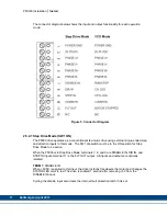
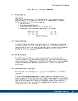
The connector diagram below shows the input and output functionality for each operation
mode:
Figure 5: Connector Diagram
2.5.4.1 Step Drive Mode (SW1 ON)
The P5000 drive operates as a conventional step motor drive using external single-ended step
and direction inputs in this mode. The SW1 dip switch must be in the ON position for Step
Drive Mode to be active.
When the P5000 is in Step Drive Mode, terminals 7, 8, and 9 are DISABLE IN, DIR IN, and
STEP IN inputs; terminal 11 is the FLT OUT output. All inputs and outputs are optically
isolated.
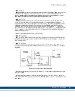
TERM 7:
DISABLE IN
When +5VDC is applied to this input, the drive instantly freewheels the motor and changes the
STATUS LED color to red. The drive is enabled 1 second after re5V from the
DISABLE IN input.
Cycling the disable input also clears the internal fault protection latch if it is set.