


P50330 Installation
│
Install
Kollmorgen | April 2013
18
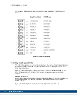
TERM 8:
DIR IN
This single-ended input sets motor direction while the STEP IN input is cycled. When +5VDC
is applied to the DIR IN input, the motor rotates in the counter-clockwise direction. When
0VDC is applied, the motor rotates in the clockwise direction. DIR IN must be true for 200
nsec before and after the STEP IN pulse edge. Single-ended signal.
TERM 9:
STEP IN
This single-ended input moves the motor one increment of motion per input pulse. The
increment of motion is defined by the pulse multiplier. The motor always moves with 1/10
TH
microstep smoothness at any input pulse resolution setting. The drive uses a phase-locked
loop pulse multiplier to synthesize step resolution. As an example, when the input pulse
resolution set to full step and the external indexer provides 200 steps per rev to the P5000
drive, the multiplier generates 10 output pulses for every input step pulse. The drive then takes
ten 0.18-degree steps to synthesize a smooth 1.8-degree step. For additional information,
please see section 3.1.3.1.
The step pulse width should equal 1 µsec minimum.
TERM 10:
COMMON
This is the opto-isolator ground return terminal. The STEP IN, DIR IN and DISABLE IN opto-
isolator LED cathodes go to this terminal. The FLT OUT opto-isolator transistor's emitter also
goes to this terminal.
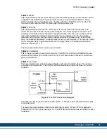
TERM 11:
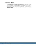
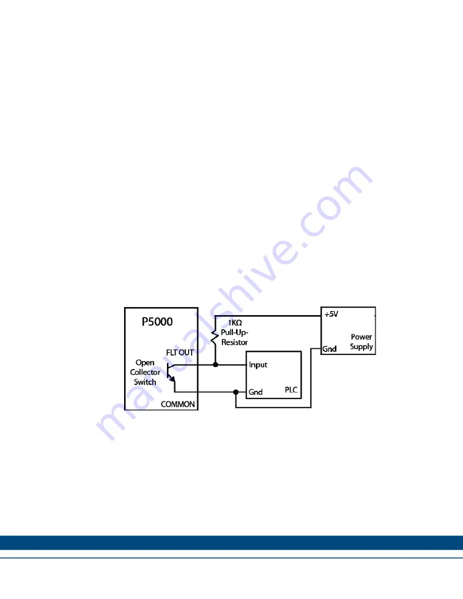
FLT OUT
This opto-isolated open collector output indicates a drive fault condition (logic '0') such as a
mis-wired or shorted motor. The STATUS LED will illuminate red when the drive is in a fault
condition.
Figure 6: FLT OUT Connection Diagram
The STATUS LED is located just above DIP switch 10. Please refer to the STATUS LED blink
code table below.
The fault output also indicates when the disable input is active. When +5VDC is applied to
DISABLE IN, FLT OUT goes low (logic ‘0’). The STATUS LED will illuminate red when the drive
is disabled.