


P50330 Installation
│
Install
19
Kollmorgen | May 2012
19
Kollmorgen | April 2013
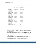
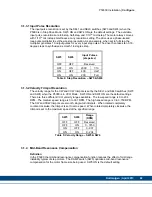
Solid Green
Step & Dir MODE: 20–75VDC Power applied.
VCO MODE: 20–75VDC Power applied &
zero speed.
Flashing Green,
Green, Green, Pause
VCO MODE only: Motor rotating CW
direction.
Flashing Red, Red,
Red, Pause
VCO MODE only: Motor rotating CCW
direction.
Solid Red
Step MODE only: Drive is Disabled. No power
to the motor.
Table 1: STATUS LED blink codes
2.5.4.2 VCO Mode (SW1 OFF)
The P5000 drive uses its integral velocity controlled oscillator function in this mode. The
internal digital frequency generator is the source of motor speed. The SW1 dip switch must be
in the OFF position for VCO Mode to be active.
When the P5000 is in VCO Mode, terminals 7, 8, and 9 are RUN/STOP, CW JOG, and CCW
JOG inputs; terminal 11 is the MOTOR STOPPED output.
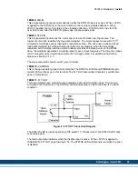
TERM 7:
RUN / STOP SWITCH
This input (marked DISABLE IN) operates the RUN / STOP switch. Ap5VDC to this
input causes the motor to accelerate at a rate set by the ACCEL trimpot to the speed set by
the CW or CCW trimpots. Re5VDC from this input causes the motor to decelerate to
zero speed at a rate set by the ACCEL trimpot.
TERM 8:
CW JOG SWITCH
This input (marked DIR IN) operates as the clockwise Jog switch. To operate the motor in the
clockwise dir5VDC must be applied to this input.
TERM 9:
CCW JOG SWITCH
This input (marked STEP IN) operates as counter-clockwise Jog switch. To operate the motor
in the counter-clockwise dir5VDC must be applied to this input.
TERM 11:
MOTOR STOPPED
This opto-isolated open collector output (marked FLT OUT) indicates when motor comes to a
stop (logic '0'). A period of time will elapse anytime the RUN / STOP input commands the
motor to decelerate to a stop. This output indicates only when the motor is actually stopped.