6
Please note the following when connecting logic power supply:
• Input current of up to 2A is required. If the brake relay is used, current of up to 4A
must be supplied.
• Check your motor holding brake amperage requirements in order to size the 24 Vdc
power supply.
• If STO is not needed, then pin 3 must be connected directly with +24 Vdc. The STO
is then bypassed and cannot be used.
• Consult the installation manual for the proper wiring and use of STO.
Step 3: Connect Motor Power (X2 Connector)
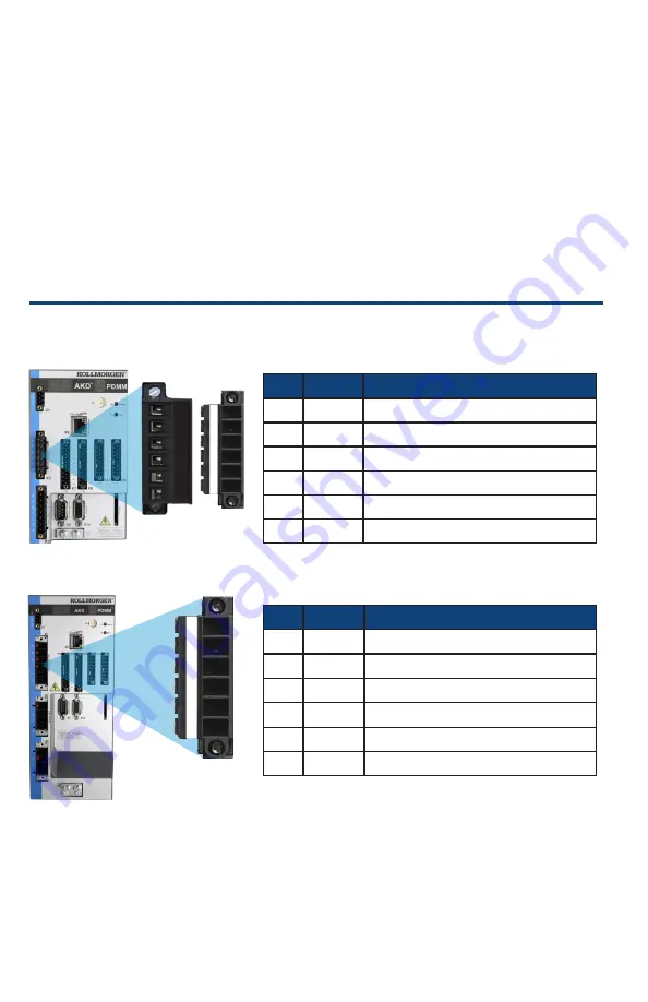
Wire the motor power cable to the X2 mating connector according to
Figures 4
,
5
, and
6
as appropriate.
Figure 4. Connector X2, AKD PDMM- xxxx06
Figure 5. Connector X2, AKD PDMM-xxxx07
Pin Signal Description
1
-Br
Motor holding brake, negative
2
+Br
Motor holding brake, positive
3
PE
Protective earth (motor housing)
4
U
Motor phase U
5
V
Motor phase V
6
W
Motor phase W
Pin Signal
Description
1
-Br
Motor holding brake, negative
2
+Br
Motor holding brake, positive
3
PE
Protective earth (motor housing)
4
U
Motor phase U
5
V
Motor phase V
6
W
Motor phase W
—
Br +Br PE U V W
-Br +Br PE U
V
W
12A
3-6A
AKD PDMM Quick Start | Connect Logic Power and STO
-Br +Br PE U
V
W
3-12A


