8
3.4 Balancing
Danger
Rotating parts
Severe injuries
► Secure feather keys against being ejected
The balancing type is indicated on the shaft end face of the motor shafts in accordance with DIN ISO
8821:
•
Balancing with a half key “H”
•
Balancing with a full key “F”
Observe the appropriate balancing type when installing the drive element!
3.5 Insulation resistance check
Before commissioning of the motor, or after a longer storage period or downtime (more than 6
months), the insulation resistance of the winding should be checked. Check the winding against mass
by means of an insulation resistance measuring device (DC voltage at least 500 V). If the minimum
insulation resistance at a winding temperature of 25 °C is smaller than 30 MΩ, or smaller than 1 MΩ at
a winding temperature of 75 °C, the motor winding should be dried until the required minimum
insulation resistance is reached. The winding temperature should not exceed 80 °C in this regard!
Loosen the bearing plate, so that an air exchange can be carried out with closed motors. After the
winding has been dried out, the bearing needs to be serviced (see corresponding chapter!).
3.6 Electrical connection
The mains voltage and frequency must match the data on the rating plate. Voltage differences of ±5%
and/or frequency differences of ±2% are permissible as described in sector A in accordance with EN
60034-1. We ask that you note this when connecting the motors.
Motor switch-off must be done through complete disconnection of all phases from the power supply.
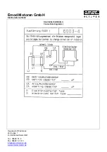
A connection diagram is enclosed with each motor upon delivery. Connection of the motor and the
control system,as well as overload protection and earthing, must be done in accordance with the VDE
and installation instructions and the EVU provisions.
The direction of rotation of the shaft end on the output side must be checked before commissioning.
Reversal of the direction of rotation should be done in accordance with the attached connection
diagram.
The insertion parts intended for tension relief or as anti-rotation protection for the supply lines must be
used properly. Seal any openings which are not required.
Tightening torques for terminal board connection screw connections see page 11.
3.7 Motor protection
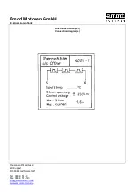
3.7.1 Temperature switch NC
If a temperature monitor is provided as a temperature switch NC for motor protection, then this must
be connected in series with the auxiliary circuit in accordance with the connection diagram (min. 25
...... max. 250 V 1.6 A).
Содержание N630.12
Страница 65: ...13...
Страница 67: ...15 9 Documents provided Circuit diagram...
Страница 69: ......
Страница 70: ...1 Operating manual for single phase motors Frame size 56 112 EHB EARZ Issue 1 0 11 19 All rights reserved...
Страница 82: ...13...
Страница 84: ...15 9 Documents provided Circuit diagram...
Страница 87: ......
Страница 88: ...KNF worldwide You can find our local KNF partners at www knf com...


