Diaphragm pump N630.12
Servicing
Translation of Original Operating and Installation Instruction, english, KNF 318761-318764 02/22
45
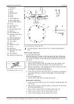
4. On the suction side and pressure side, fit the new valves (20) and
valve limiters (19) with the slotted cap screw (21, tightening torque:
2 Nm).
Make certain that the valves (20) and valve limiters (19) are placed
symmetrically on the valve hole.
5. For two-headed pumps:
Perform steps 1 to 4 for the second pump head.
Fitting the pump head
1. Place the intermediate plate (18) on the housing (14) in accordance
with the felt-tip pen marking (diaphragm should be held in the middle
position by holding the fan blade).
2. Insert the two new O-rings (2) in the intermediate plate (18).
3. Insert the new O-ring (3) in the intermediate plate (18).
4. Place the head plate (1) on the intermediate plate (18) in accordance
with the felt-tip pen marking and the orientation predefined by the cylin-
drical pins (25).
5. Screw in the hexagon socket head cap screws (24) by one to two
turns.
6. Tighten the hexagon socket head cap screws (24) crosswise (tighten-
ing torque: 11 Nm).
7. Check the pump for smooth running by turning the fan.
8. For two-headed pumps:
Perform steps 1 to 7 for the second pump head.
9. Install the motor fan cover (see Chapter
4 Product description and func-
) according to the felt-tip pen marking.
10. For two-headed pumps:
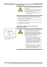
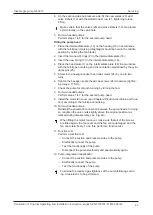
Reinstall the pneumatic connection between the pump heads. In doing
so, retighten the union nuts slightly above the original position (as
marked during disassembly, see Fig. 20).
When fitting the motor fan cover, make sure that all of the screws
are fitted again, the fan cover and the fan are undamaged, and the
fan can rotate freely. To do this, perform a function test.
11. Function test
Perform a function test.
– Connect the suction and pressure sides to the pump.
– Electrically connect the pump.
– Test the functionality of the pump.
– Disconnect the pump electrically and pneumatically again.
12. Pump integrated in application
– Connect the suction and pressure sides to the pump.
– Electrically connect the pump.
– Test the functionality of the pump.
To ensure the required gas tightness of the pump following servic-
ing, a leak test is to be performed.
Содержание N630.12
Страница 65: ...13...
Страница 67: ...15 9 Documents provided Circuit diagram...
Страница 69: ......
Страница 70: ...1 Operating manual for single phase motors Frame size 56 112 EHB EARZ Issue 1 0 11 19 All rights reserved...
Страница 82: ...13...
Страница 84: ...15 9 Documents provided Circuit diagram...
Страница 87: ......
Страница 88: ...KNF worldwide You can find our local KNF partners at www knf com...


