


25
6. Preparing for First Start-up
Only appropriately qualified and trained installation and
start-up team can perform first start-up of the unit after the
ventilation or air conditioning installation has been com-
missioned.
It is a requirement that start-up be preceded by the follow-
ing operations:
• checking whether all the unit’s modules are connected
together and suspended correctly,
• checking whether the air installation has been connected
correctly and there are no leaks,
• checking hydraulic and Freon installations for leaks, their
readiness for work and whether the heating or cooling
medium is available at start-up,
• checking whether power connections are correct, check-
ing wiring and operational readiness of power receivers,
• checking correct installation of traps and the system for
condensate drain from drip trays,
• checking correct installation of automation elements.
Moreover, it is necessary to clean the interior of unit cas-
ings and ducts cooperating with them. One should also
make sure that the parts of the units, hydraulic installa-
tion and automation fittings have not been damaged
during installation works.
6.1 Power Supply Installation
It should be checked whether power installation and safe-
ties of all power receivers have been connected properly.
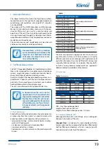
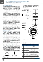
6.2 Filters
Remove protective foil from filters. Make sure the condition
of the filters is correct (leakproofness, fixing on the tracks).
Set the pressure switches correctly (if they have been re-
moved), determining the admissible final drop of static
pressure on the filter – when the drop has been exceeded,
it is recommended that the filter be renewed.
The table presents the admissible pressure drop for the
filters used:
Table 5 Filter Type and Class
Filter type and class
Admissible Pressure Drop
(according to PN-EN13053:2008)
Cassete Filter G1÷G4
150 Pa
Bag Filter M5÷F7
200 Pa
Bag Filter F8÷F9
300 Pa
6.3 Water Heaters
The following should be checked:
• condition of exchanger lamellas (mechanical damage,
contamination),
• correct connection of supply and return pipeline,
• fixing of antifreeze thermostat capillary, which should
be undone on the heater,
• set the antifreeze thermostat to +4°C,
• whether the exchanger is free of air.
6.4 Electric heaters
The following should be checked:
• condition of electric heating elements of the heater, if they
are not damaged or are not in contact with the elements
inside the heating module,
• correctness of power connections,
• correct connection of protective thermostat.
6.5 Water and DX cooling coils
The following should be checked:
• condition of exchanger lamellas (mechanical damage,
contamination),
• correct connection of supply and return pipeline,
• position of condenser with regard to airflow direction,
• correct fixing of the trap, trapping height and permea-
bility of the drain installation. Before start-up of the unit
the trap must be filled with water.
• whether the exchanger is free of air.
6.6 Cross-flow Counter-current Exchanger
The following should be checked:
• condition of exchanger lamellas (mechanical damage,
contamination),
• operation of the bypass air damper
• correct fixing of the trap, trapping height and permea-
bility of the drain installation. Before start-up of the unit
the trap must be filled with water.
6.7 Fan section
Prior to start, it is necessary to make a thorough inspection
of the fan section module. Make sure there are no objects
in the vicinity of the fan that could enter the inside of the
fan rotor.
Check if the rotor turns without resistance (e.g. adjacent
elements scraping against one another).
Prior to starting the motor it is necessary to check:
• the motor’s power connection (the voltage of the power
supply network has to be the same as the voltage on the
motor’s nameplate)
• the condition of the earth wire between elements of the
fan section and the unit’s casing,
• the power cables inside the module must be firmly fixed
to the elements of the construction so as to prevent them
from getting close to movable elements (rotor),
• the direction of the rotor’s revolutions (to be checked by
impulse start of the motor) has to comply with the label-
ling on its casing. In case of non-compliance the direc-
tion of rotating supply power phases should be shifted
by swapping any two phases in the terminal box,
• setting of the inverters for fan start-up/warm-up time
(should be a minimum of 30 sec.).
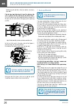
In order for the rotor to be able to rotate freely, make sure
the slot between the rotor and the outlet nozzle is appro-
priate.
The slot can be adjusted as follows:
• loosen 6 bolts and move the outlet nozzle vertically,
• move the rotor horizontally together with the motor, tray,
Содержание EVO-T
Страница 2: ...SERWIS SERVICE 4858 7839950 51 4858 7839888 48 782800566 serwis klimor com...
Страница 17: ...15 NOTATKI...
Страница 18: ...SERWIS SERVICE 4858 7839950 51 4858 7839888 48 782800566 serwis klimor com...
Страница 33: ...31 NOTES...
Страница 34: ...SERWIS SERVICE 4858 7839950 51 4858 7839888 48 782800566 serwis klimor com...
Страница 35: ...KLIMOR EVO T...
Страница 41: ...39 Fig 05 06 5 6 5 7 07 P 08 P 5 8...
Страница 43: ...41 5 11 EVO T 6 a 6 1 6 2 5 PN EN13053 2008 G1 G4 150 Pa M5 F7 200 Pa F8 F9 300 Pa 6 3 4o C 6 4 6 5 DX 6 6 6 7...
Страница 44: ...EVO T 42 30 6 4 o 2 5 2 5 2 5 2 5 A A 11 EC 4 M6X16 K R3G M6x16 M6 12 EC 7 30 30...
Страница 46: ...EVO T 44 8 3 4 DX 4 50 0 8 4 8 5...
Страница 48: ...EVO T 46 13...
Страница 49: ...47...
Страница 50: ...EVO T 48...
Страница 51: ......