


21
4. Transport, Storage
4.1 General Requirements
EVO-T units are delivered to the installation site in the form
of separate blocks together with a set of connecting ele-
ments. They are secured with foil for transport.
Unloading from the transport vehicle and transport to the
building site is done manually with the use of a pallet-lift
truck or forklift truck. When transporting the unit blocks,
one should see to it that they are lifted and lowered gently.
EVO-T unit modules should not be transported and stored
when they rest on one of the sidewalls of the casing.
It is recommended that the modules be transported on the
wall opposite to the inspection panels (“on the back”).
Immediately after delivery its completeness should be
checked.
Any damage caused as a result of improper transport
and storage shall not be covered by the manufacturer’s
warranty.
Storage conditions:
• maximum relative air humidity of <80% in a temperature
of 20ºC
• temperature from -20ºC to 40ºC
• environment free of caustic dusts, gases and fumes and
chemically active substances with corrosive properties
5. Installation of the Unit on Site
5.1 Location
The unit should be mounted in a way as to ensure con-
nection to outer installations (ventilation ducts, pipelines,
cable tracks), avoiding collision with inspection panels. In
order to facilitate assembly, operation and servicing of the
units and renewal of elements and subassemblies in case
of failure, it is necessary to maintain appropriate spaces be-
tween the servicing side and fixed elements of the room’s
development (walls, load-bearing columns, binders etc.).
The above-mentioned spaces are also recommended be-
cause of the outer sizes of the elements of the fittings sup-
plying the heaters and coolers, and should not be smaller
than 500mm.
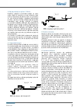
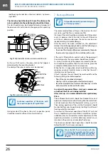
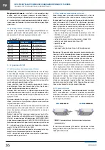
5.2 Suspending the Unit
5.2.1 Compact Units
The unit is to be suspended with the use of handles mount-
ed on the sides of the casing. A M8 threaded bar is inserted
into the lower part of the handle (U1) and a nut with a wash-
er is screwed on. Next, the bar is inserted into the groove of
the upper part of the handle (U2), and at the same time they
are joined together by pushing the U1 element into the U2
element at the bottom. The use of M8 threaded bars enables
easy and quick suspension and levelling off of the particular
modules of the unit. The M8 threaded bars are not delivered.
The minimum retained distance of the upper surface of the
unit to the partition should be 20mm (Fig. 02)
20
U2
U1
PRĘT M8
Fig. 02
Suspending the EVO-T unit in the compact version
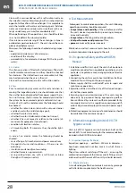
5.2.2 Modular Units
Modular units in intake or outlet systems should be sus-
pended, just like compact units, with the use of handles
mounted on the sides of the casings. The modules are sus-
pended independently. Prior to connection, an adhesive
seal should be stuck on the front surface of one of them
(unless it has been stuck in factory). The modules are to be
bolted together using the handles on which the units are
hanging. They are to be bolted together on both sides of
the casing with a double set of M6x60 bolts.
Fig. 03
Suspending the EVO-T unit in the modular version
Modular units in intake-outlet systems with crossflow
exchanger are to be suspended with the use of handles
mounted on the sides of the casings.
The modules should be interconnected with the use of four
interior corners located on the front surfaces. Remember-
ing to place a seal on one of the front surfaces, we bolt to-
gether both modules with M6x16 bolts (Fig. 04b).
Adjacent modules, having their sidewalls in contact, are to
be bolted together with M6x70 bolt connectors (Fig. 04a).
The bolts should go through the corner openings and
through the casing.
Connecting the casings should be preceded by removal of
interfering handles. Such a system of two modules is to be
suspended with the use of the remaining four handles.
M6x60 BOLT CONNECTOR
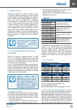
Содержание EVO-T
Страница 2: ...SERWIS SERVICE 4858 7839950 51 4858 7839888 48 782800566 serwis klimor com...
Страница 17: ...15 NOTATKI...
Страница 18: ...SERWIS SERVICE 4858 7839950 51 4858 7839888 48 782800566 serwis klimor com...
Страница 33: ...31 NOTES...
Страница 34: ...SERWIS SERVICE 4858 7839950 51 4858 7839888 48 782800566 serwis klimor com...
Страница 35: ...KLIMOR EVO T...
Страница 41: ...39 Fig 05 06 5 6 5 7 07 P 08 P 5 8...
Страница 43: ...41 5 11 EVO T 6 a 6 1 6 2 5 PN EN13053 2008 G1 G4 150 Pa M5 F7 200 Pa F8 F9 300 Pa 6 3 4o C 6 4 6 5 DX 6 6 6 7...
Страница 44: ...EVO T 42 30 6 4 o 2 5 2 5 2 5 2 5 A A 11 EC 4 M6X16 K R3G M6x16 M6 12 EC 7 30 30...
Страница 46: ...EVO T 44 8 3 4 DX 4 50 0 8 4 8 5...
Страница 48: ...EVO T 46 13...
Страница 49: ...47...
Страница 50: ...EVO T 48...
Страница 51: ......