32
DM8000 User Manual
When
Gang Controls
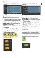
is enabled, the Mute Control Dialog Box will show a single
Mute control for all channels:
Mute Control Dialog Box with Gang Controls enabled
Mute modules can also be set up with logic control terminals by going to the
Parameters Dialog Box and enabling the
Control Inputs
option:
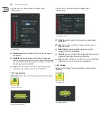
Mute Parameter Dialog Box with Control Inputs enabled.
When
Control Inputs
is enabled, the Mute Component Object will display logic
control terminals along the top, one logic terminal for each audio channel:
Mute Component Object with Logic Terminals
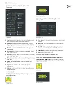
Gang Controls and Control Inputs can both be enabled at the same time, in which
case the Mute Component Object will display a ‘G’ and a single logic terminal
along the top:
Mute Component Object with Ganged Logic Terminal
3.9.5 Logic Gates
Logic Gates
can be placed between the logic output and logic input terminals
of other modules in the Build Window. Logic Gates can also be used to manage
control signals from GPIO connections and integrate those GPIO signals into the
DSP processing.
Logic Gate Module Icons
Logic Gate Component Objects
Logic Gate modules function in the following ways:
•
NOT
inverts logic command cues (e.g., a HIGH input exits the module as a
LOW output, while a LOW input is inverted into a HIGH output).
•
AND
triggers a single output of matching polarity when ALL of the inputs are
the same (i.e., when all inputs are HIGH, the module produces a single HIGH
output; When all inputs are LOW, the module produces a single LOW output).
•
NAND
produces a single LOW output when ALL inputs are HIGH, while one or
more LOW inputs triggers a HIGH output.
•
OR
produces a single LOW output when ALL inputs LOW, while one or more
HIGH inputs triggers a HIGH output.
•
NOR
produces a single HIGH output when ALL inputs are LOW, while one or
more HIGH inputs triggers a LOW output.
•
XOR
produces a single LOW output when ALL inputs are LOW or HIGH.
HIGH inputs triggers a single HIGH output, but only when NOT ALL inputs
are HIGH (e.g., in a four-input XOR module, when three out of four inputs are
HIGH, the output will be HIGH; However, whenever ALL four inputs are HIGH,
the output will be LOW).
•
Flip Flop
behaves like a toggle or latching switch where a HIGH input
changes the output state, depending on how the output has been set
(e.g., when the output is set to HIGH, a HIGH input changes the output
to LOW; When the output is set to LOW, a HIGH input changes the output
to HIGH).
•
Logic State
modules act as manual toggle or latching switches. Logic State
modules to not have input terminals.
NOTES
:
•
Only
NOT
and
Flip Flop
modules have matching one-to-one inputs for every
output, while other gate types have multiple inputs for a single output.
•
Only
Flip Flop
and
Logic State
modules have Control Dialog Boxes, which
are used to set these modules’ initial HIGH or LOW states.
Содержание DM8000
Страница 65: ......


