background image


Chapter 1 Introduction 

1.1

Introduction

This manual applies to the service and maintenance of PT7200 

series of FM portable radios, and is designed for the engineers and 

professional technicians that have been trained by Kirisun. In this 

manual you can find all the information of product service. Kirisun 

reserves the rights to modify the product structure and specification 

without notice in order to enhance product performance and quality. 

You can also log on our website www.kirisun.com to download the 

latest service manual or contact your local dealer or us. 

Read this manual before repairing the product.

1.2 Service Precautions 

Safety

Avoid skin contacting with the antenna connector and PCB.

Do not reverse the power polarities.

If signal input at antenna connector is bigger than 

20dBm(100mW), it may cause damage to the radio.

Do not turn on the power before the antenna and load 

connection is completed.

Do not use the radio if the antenna has been damaged. 

Contacting the damaged antenna will cause slightly burning on the 

skin. 

Electromagnetism Interference 

It's prohibited to use or repair the radio in the following 

places:

Hospital, health center, air port 

Any area with a potentially explosive atmosphere (where the air 

contains gas, dust and smog, etc.), such as the storage or 

transportation facilities of fuel or chemicals.

Any area of dynamite or exploder.

It's recommended to avoid using or repairing the radio in the 

following places:

It's recommended to avoid using the radio in a car that is 

moving. The radio wave might interfere the auto engine and cause it 

to stop working.

Component Replacement

All the components used in repair service should be supplied by 

Kirisun.

Other components of the same models available on the market 

are not surely able to use in this product and we do not guarantee 

the quality of the product using such components.

Please fill in a component application forms if you want to apply 

for any components from Kirisun. 

The following is one sample form that might be used to apply 

for any components from Kirisun.


                                Component Application

1.3 Service

All the Kirisun products are subject to the service warranty. 

The main unit of the radio is guaranteed for free service of 18 

months. Accessories (such as battery pack, power adapter, antenna 

or charger) are guaranteed for free service of 6 months. Earphones 

are wearing parts and out of warranty. 

In one of the following situations, charge-free service will not be 

available.

No valid service warranty or original invoice. 

Malfunction caused by disassembling, repairing or 

reconstructing the radio by the users without permission.

Wearing and tearing or any man-made damage such as 

mechanical damage, burning or water leaking. 

Product serial number has been damaged or the product 

trademark is difficult to identify.

After the warranty expires, lifetime service is still available. And 

we also provide service components to service stations and service 

staff. 

         Chapter 2 Radio Overview and Function Keys

2.1 Radio Overview

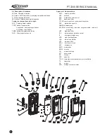
                                        Figure2-1


LED Indicator

Lights red while transmitting signals; lights green while receiving 

signals.

Flashes red while in low battery power during transmitting.

 Channel Selector

Rotate it to select channel 1-16.

 Power/Volume Switch

Turn clockwise till a click is heard to switch on the radio. 

Turn counterclockwise till a click is heard to switch off the radio.

Rotate it to adjust the volume after turning on the radio.

 PTT (Push-to-talk)

To make a call, press and hold the PTT button, then speak into 

the microphone in normal voice. 

Release the PTT button to receive a call.


Side key 1

Programmable function button: Press it to activate the 

programed auxiliary function.

 Side key 2

Programmable function button: Press it to activate the 

programed auxiliary function.


Top Button

Programmable function button: Press it to activate the 

programed auxiliary function. 

 Microphone/Speaker Jacks

For connecting the optional Microphone/Speaker.

Compo

Radio  


     M

   o del/


Mat e  r i a  l  Serial


Qua

N o .

No.

pecifications

nent

S

ntity

Model      


PT7200-01 FET     Q68       RD07MVS1    105-RD07MV-001

1

PT7200-01 Triode    Q57      2SC5108(Y)    104-SC5108-001

1

PT7200 SERVICE MANUAL

1

Содержание PT7200-01

Страница 1: ...PROFESSIONAL TWO WAY RADIO PT7200 V071215 FM PORTABLE RADIO SERVICE MANUAL ...

Страница 2: ...s the copyright of the radio outward structure circuit design Kirisun Electronic Shenzhen Co Ltd owns the copyright of this service manual Unauthorized publication is prohibited Kirisun Electronic Shenzhen Co Ltd owns the trademarks KIRISUN Contents Chapter 1 Introduction 1 Chapter 2 Radio Overview and Function Keys 1 Chapter 3 Electric circuit 2 Chapter 4 Function Description and Parameter Settin...

Страница 3: ...n The following is one sample form that might be used to apply for any components from Kirisun Component Application 1 3 Service All the Kirisun products are subject to the service warranty The main unit of the radio is guaranteed for free service of 18 months Accessories such as battery pack power adapter antenna or charger are guaranteed for free service of 6 months Earphones are wearing parts a...

Страница 4: ...er the 2 IF signal is amplified and its amplitude is limited inside U9 and then filtered at porcelain filter wideband CF4 Nattowband 3 450kHz and then sent to U9 to demodulate the output audio signals which are finally th output from the 9 pin of U9 Receiver Audio Signal Processing IC13 IC12 IC16 IC15 and their peripheral circuit compose the receiver audio signal processing circuit After being sen...

Страница 5: ...ed by MCU according to the preset channel frequency The oscillation frequency from VCO is sent to IC1 and demultiplied by programmable frequency demultiplier and compared with reference frequency to acquire the error signals Then pass the low pass filter and are sent to VCO to change VCO oscillation frequency to the preset value and then VCO is locked N F F VCO R N Frequency demultiplication times...

Страница 6: ...sitivity adjusting voltage output power control V DTMF Tone output beep output Tone decoding input EEPROM data input output EEPROM clock Gnd Gnd 8 BSHIFT 9 SV 10 RESET 11 XOUT 12 VSS 13 XIN 14 VCC 15 NC 16 VDET 17 RDT 18 TCLK 19 SCLK 20 QT DQT 21 TDATA 22 StCtrl 23 DI O 24 QTVCO 25 DIR 26 APC 27 NC 28 QTTCXO 29 TXD 30 RXD 31 NC 32 APC SW 33 TXD0 34 RXD0 35 DC SW 36 TX W N 37 RX SW 38 TX SW 39 NC 4...

Страница 7: ...input DTMF input Gnd NC 5V 5V NC External and internal MIC switch High pass filter switch Function description Phase locked loop chip APC voltage comparison drive Receiver s 2nd local oscillation 2nd IF amplifier amplitude limit demodulation noise amplification Audio processing MIC amplification Receiver audio power amplifier E2PROM memory channel frequency data function setting parameter debuggin...

Страница 8: ...ing PTT key the radio will transmit signals on the channel where the last transmitting was made 3 Last used channel current channel when response channel is enabled If pressing PTT or the CALL key or enabling VOX transmitting during the scanning the radio will transmit signals on the channel where the last transmitting was made If pressing PTT or the CALL key or enabling VOX transmitting when the ...

Страница 9: ...for squelch on switch the green light will be on and the radio is in the monitoring status 4 1 8 5TONE signaling 5Tone has 9 encoding formats CCIR1 CCIR2 ZVEI1 ZVEI2 ZVEI3 EEA EIA USER DEFINED1 and USER DEFINED2 The last two formats are customized modes 1 5tone decoding The decoding template is the 5tone decoding template If the decoding template is the same to that of encoding the decoding will b...

Страница 10: ...ritten in with the editing data open the data backup and rewrite the backup into the radio 5 Model information is important radio data and is prohibited to modify 4 3 Computer Test Mode As shown in figure 4 1 connect the radio to the radio communication port with the specified testing cable Warning Before enter the computer test mode connect a HF load of 50 to the radio antenna connector or connec...

Страница 11: ... the aluminum alloy frame out of the casing See Figure 5 5 5 4 Remove the Chassis from the Main Board 1 Remove the screw 2 Melt the solder at the antenna point with a electric soldering iron and take off the main board 3 Take away the two screws and the antenna connector See Figure 5 6 After the aforesaid operations you can carry out corresponding service or debugging according to the actual situa...

Страница 12: ...level 1 500mV Attenuation 40dB or 50dB Supporting power Higher than 10W Frequency range 10MHz 1000MHz Output level 0 1uV 32mV 127dBm 17dBm Frequency range DC 20MHz Test range 10mV 20V Test range 10mV 10V PT7200 SERVICE MANUAL 1 2 3 4 5 6 7 8 9 10 11 12 13 14 15 16 17 18 19 20 21 22 23 24 25 26 27 28 29 30 31 32 33 34 35 36 37 38 39 40 41 42 10 KEY PTT SCREW 2 4 RUBBER KEY PTT METAL DOME PCB FOR PT...

Страница 13: ...ansmitting low battery warning in the computer debugging mode Set the power supply voltage at 6 8V and press start and then end 3 Receiving Sensitivity adjustment Adjust the sensitivity in the computer debugging mode Make the sensitivity of all frequency points the highest provided the sensitivity is the highest the bigger computer debugging data the better Squelch adjustment Adjust squelch in the...

Страница 14: ...d flash and no transmitting power 15 Starting time of transmitting should be 55ms Voltage for aforesaid tests 7 5V 0 1V in room temperature Frequency range 136MHz 174MHz 350MHz 400MHz 400MHz 470MHz 450MHz 520MHz 1 Sensitivity 116dBm 0 35uV wideband narrowband Hi Med Low frequency points 14dB SINAD MOD 1kHz DEV 3kHz wideband 1 5kHz narrowband 2 Distortion half audio power 8 Max audio power 20 16ÙSp...

Страница 15: ...arging When the battery voltage reaches 9 6V 0 2V the battery will be deemed as full and the charging will be stopped Li ion battery pre charging when the voltage 6 5 0 1V when the battery voltage reaches 6 5 0 1V the charging turns to rapid charging Charging process checking battery voltage battery temperature rise V charging time max Battery temperature Min battery voltage 5 5V 0 1V for nickel h...

Страница 16: ...ix 1 Abbreviations AMP amplify amplifier ANT antenna APC automatic power control BPF band pass filter CTCSS continuous tone control squelch system DCS digital code squelch DEMOD demodulation E2PROM electrically erasable programmable read only memory HPF high pass filter IDC instantaneous deviation control IF intermediate frequency LED Light Emitting Diode LNA low noise amplifier LPF low pass filte...

Страница 17: ...2 Spare List 604 072000 R01 CABINET ASM 304 30040G R01 SPECIAL SCREWM3 0 4 604 072000 R02 EARPHONE PCBASM 201 007200 R08 EARPHONE COVER 203 000558 R02 VR NUT 203 007200 R08 ENCODER NUT 203 007200 R07 NUT FOR ANTENNA SOCKET 604 072000 R03 VR KNOBASM 604 072000 R04 ENCODER KNOBASM 202 007200 R04 RUBBER KEY PTT 201 007200 R04 KEY PTT 202 007200 R09 POGO PIN SOCKET MAIN PCB ASM 604 072000 R07 ALCABINE...

Страница 18: ...C ROHS Chipdiode 1SR154 400 ROHM ROHS Chipvarialblecapacitordiode 1SV278 ROHS Chipvarialblecapacitordiode 1SV305 ROHS Chipvarialblecapacitordiode 1SV325 ROHS Chipswitchdiode 0603 MA2S111 PANASONIC ROHS Chip switchdiode DAN222 ROHM ROHS Chipdiode Wavebandswitch HSC277 HITACHI ROHS ChipHFswitchdiode 0603 HVC131 HITACHI ROHS Chipvarialblecapacitordiode HVC376B ROHS ChipLED 0603 green H19 213SYGC ROHS...

Страница 19: ...2 220K 5 ROHS Chipresistor 0402 24K 5 ROHS Chipresistor 0402 2 7K 5 ROHS Chipresistor 0402 27K 5 ROHS Chipresistor 0402 270K 5 ROHS Chipresistor 0402 330R 5 ROHS Chipresistor 0402 3 3K 5 ROHS Chipresistor 0402 33K 5 ROHS Chipresistor 0402 330K 5 ROHS Chipresistor 0402 390R 5 ROHS Chipresistor 0402 3 9K 5 ROHS Chipresistor 0402 39K 5 ROHS Chipresistor 0402 390K 5 ROHS Chipresistor 0402 43K 5 ROHS C...

Страница 20: ...ipcapacitor 0402 13P 5 50V C0G ROHS Chipcapacitor 0402 15P 5 50V C0G ROHS Chipcapacitor 0402 150P 5 50V C0G ROHS Chipcapacitor 0402 18P 5 50V C0G ROHS Chipcapacitor 0402 180P 10 50V X7R ROHS Chipcapacitor 0402 1800P 10 50V X7R ROHS Chipcapacitor 0402 1P 0 25P 50V C0G ROHS Chipcapacitor 0402 20P 5 50V C0G ROHS Chipcapacitor 0402 22P 5 50V C0GROHS Chipcapacitor 0402 220P 5 50V C0G ROHS Chipcapacitor...

Страница 21: ...0 1P 50V C0G ROHS Chip capacitor 0603 10P 5 50V C0G ROHS Chip capacitor 0603 100P 5 50V C0G ROHS Chip capacitor 0603 1000P 10 50V X7R ROHS Chip capacitor 0603 0 01uF 10 50V X7R ROHS Chip capacitor 0603 0 1uF 10 50V X7R ROHS Chip capacitor 0603 11P 5 50V C0G ROHS Chip capacitor 0603 120P 5 50V C0G ROHS Chip capacitor 0603 15P 5 50V C0G ROHS Chip capacitor 0603 16P 5 50V C0G ROHS Chip capacitor 0603...

Страница 22: ...NJ 47nH 5 0603 ROHS Chip inductor MLF1608DR47K 470nH 10 0603 ROHS Chip inductor MLF1608DR56K 560nH 10 0603 ROHS Chip inductor MLG1608B82N 82nH 5 0603 ROHS Chip wire inductor C2012C 22NJ 22nH 5 0805 ROHS Chip wire inductor C2012C 39NJ 39nH 5 0805 ROHS Chip wire inductor C2012C 47NJ 47nH 5 0805 ROHS Chip wire inductor C2012C 56NJ 56nH 5 0805 ROHS Chip wire inductor FHW1008UC1R0GB ceramic core 1uH 2 ...

Страница 23: ...ode Waveband switch HSC277 HITACHI ROHS Chip HF switch diode 0603 HVC131 HITACHI ROHS Chip varialble capacitor diode HVC355B ROHS Chip regulator diode HZU5ALL HITACHI ROHS Chip LED 0603 green H19 213SYGC ROHS Chip LED 0603 red 19 21SURC S530 A2 TR8 ROHS Chip regulator diode MAZ806800L ROHS Chip triode DTA123JE ROHM ROHS Chip triode DTA144EE ROHM ROHS Chip triode DTC114EE ROHM ROHS Chip triode DTC1...

Страница 24: ...OHS Chip resistor 0402 27K 5 ROHS Chip resistor 0402 270K 5 ROHS Chip resistor 0402 3K 5 ROHS Chip resistor 0402 330R 5 ROHS Chip resistor 0402 3 3K 5 ROHS Chip resistor 0402 33K 5 ROHS Chip resistor 0402 330K 5 ROHS Chip resistor 0402 3 9K 5 ROHS Chip resistor 0402 39K 5 ROHS Chip resistor 0402 390K 5 ROHS Chip resistor 0402 470R 5 ROHS Chip resistor 0402 4 7K 5 ROHS Chip resistor 0402 47K 5 ROHS...

Страница 25: ...OHS Chip resistor 1206 0 39R 5 ROHS Volume switch RY 6932 ROHS Chip FUSE 433003 3A 32V 1206 ROHS Chip capacitor 0402 10P 0 5P 50V C0G ROHS Chip capacitor 0402 100P 5 50V C0G ROHS Chip capacitor 0402 1000P 10 50V X7R ROHS Chip capacitor 0402 0 01uF 10 50V X7R ROHS Chip capacitor 0402 0 1uF 80 20 16V Y5V ROHS Chip capacitor 0402 1uF 10 6 3V X5R ROHS Chip capacitor 0402 12P 5 50V C0G ROHS Chip capaci...

Страница 26: ... Chip capacitor 0402 8P 0 5P 50V C0G ROHS Chip capacitor 0402 0 5P 0 1P 50V C0G ROHS Chip capacitor 0402 0 75P 0 1P 50V C0G ROHS Chip capacitor 0603 10P 5 50V C0G ROHS Chip capacitor 0603 100P 5 50V C0G ROHS Chip capacitor 0603 1000P 10 50V X7R ROHS Chip capacitor 0603 0 01uF 10 50V X7R ROHS Chip capacitor 0603 0 1uF 10 50V X7R ROHS Chip capacitor 0603 13P 5 50V C0G ROHS Chip capacitor 0603 15P 5 ...

Страница 27: ...ROHS Chip inductor MLF1608A3R3K 3 3uH 5 0603 ROHS Chip inductor MLG1608B3N9ST 3 9nH 0 3nH 0603 ROHS Chip inductor MLF1608DR47K 470nH 10 0603 ROHS Chip inductor MLF1608DR56K 560nH 10 0603 ROHS Chip inductor MLG1608B6N8DT 6 8nH 0 5nH 0603 ROHS Chip inductor MLG1608BR27J 270nH 5 0603 ROHS Chip wire inductor C2012C 22NJ 22nH 5 0805 ROHS Chip wire inductor LQW2BHNR22NJ03L LQN21AR22J 220nH 5 0805 ROHS C...

Страница 28: ...ame Type Specification Accessories Battery 7 4V 1700mAH Li ion battery Hanging Loop Earphone Charger Standard charger Antenna Stubby antenna KB 70B KGS 03 Clip KME 011 KBC 70C KA PT7200 SERVICE MANUAL 26 Whip Antenna Earphone KA ...

Страница 29: ...Figure 1 PT7200 Top Board Position Mark Diagram 136 174 ...

Страница 30: ......

Страница 31: ...Figure 1 PT7200 Top Board Position Mark Diagram 400 470 ...

Страница 32: ......

Страница 33: ... 6 3v C505 33p C506 33p X6 3 6864MHz R525 1M R504 100k C604 1U 10V C603 1U 10V C595 0 033uF R346 0R C492 27p R545 220k R552 24k R544 51K C22 104 R403 2 2K R539 12k R299 12k R442 NC R502 43k R533 180k R309 10k R300 10k C584 470P C593 104 C541 1uF C21 223 C559 103 Q51 2SK1824 R397 6 8K R553 27k C406 105 R503 100k R449 33k R348 0R R374 47K R453 68K C545 1uF R441 NC R306 15k R291 22k C431 333 C599 560...

Страница 34: ...1 18k R542 18k C623 4 7u 10v C518 27P R56882k R46533k C556 1u C622 474 R425 10k R395 27k R424 0R C479 33p C620 150p R565 56k R566 56k C618 273 C415 104 C621 1u 10v C502 22p C503 22p X6 3 6864MHz R5241M R394 100k C608 1U 10V C607 1U 10V C600 0 033uF R423 0R C478 27p R332 220k R564 24k R54551K C21 0 018uF R340 10K R540 18k R299 22k R517 NC R393 100k R534 390k R309 15k R300 22k C586 470P C552 0 018uF...

Страница 35: ...Figure 7 Schematic Circuit Pane Diagram PT7200 SERVICE MANUAL 26 33 ...

Отзывы: