


PT568 Service Manual
6
EEPROM
D/A
chananl
SW
PTT
MONI
ALAR
M
PF1
C
T
C
SS/DC
S I
N
SQL
BA
T
T
V
CCN
C
T
C
SS/DC
S OUT
B
EEP
LE
DATA
CK
to PLL
VIOCE CHIP
TX/RX CONTROL
RX
D
TXD
to PC
UL
5TC
5RC
SAVE
APC CONTR
SHIFT
IC9
IC10
MCU
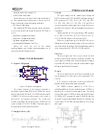
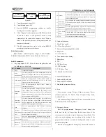
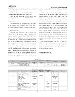
Figure 3.9 Principle of MCU Unit
MCU unit controls the operation of each unit of the radio so
that all functions can be realized.
Communicate with external PC.
Access the status data of the radio.
Control the PLL to generate Rx and Tx local oscillator
frequencies.
Obtain status parameters of current channel.
Control status of LED indicator.
Control power supply for each unit.
Check the actions of each functional key.
Generate CTCSS signal.
Generate DCS signal.
Generate power control signal.
Perform CTCSS decoding.
Perform DCS decoding.
Test and control the squelch.
Control content of voice alert.
Memory (E
2
PROM, AT24C08):
The memory is stored with channel data, CTCSS/DCS data,
other function setting data, and parameter adjusting data.
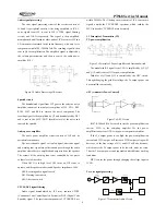
CTCSS/DCS signal encoding and decoding:
The CTCSS/DCS signal (output from pin 12) generated by
MCU is filtered by R155, R156, C242 and C243. Then the
resulting signal is divided into two parts and sent to VCO and
TCXO respectively for modulation.
The CTCSS/DCS signal from the receiver is sent to MCU (pin
49) for decoding. MCU checks if the CTCSS/DCS signal in the
received signal matches the preset value of the radio, and
determines whether to open the speaker or not.
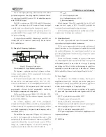
Power adjustment:
Output from pin 42 of the MCU passes through integrating
filter (R161, C317, R206, and C318), and is sent to the APC unit
to control the output power of the transmitter.
CTCSS
CTCSS (Continuous Tone Control Squelch System) is a
squelch control system which is modulated on carrier and is
guided by a continuous sub-audio signal. If CTCSS is set, the
communication between the transmitting and receiving radios can
be realized only when the two radios have set the same CTCSS
frequency. In doing this, disturbance from other signals can be
avoided.
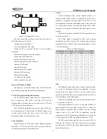
PT568 has 39 groups of standard CTCSS frequencies for your
selection. See table 3.1.
The CTCSS signal is generated by MCU, and is passed
through low pass filter consists of RC to remove high frequency
components (above 300Hz). Then the resulting signal is sent to
VCO for modulation.
Table 3.1 CTCSS Frequencies
No.
Frequency
[Hz]
No.
Frequency
[Hz]
No.
Frequency
[Hz]
No.
Frequency
[Hz]
1 67.0 11
94.8 21 131.8 31 186.2
2 69.3 12
97.4 22 136.5 32 192.8
3 71.9 13
100.0 23 141.3 33 203.5
4 74.4 14
103.5 24 146.2 34 210.7
5 77.0 15
107.2 25 151.4 35 218.1
6 79.7 16
110.9 26 156.7 36 225.7
7 82.5 17
114.8 27 162.2 37 233.6
8 85.4 18
118.8 28 167.9 38 241.8
9 88.5 19
123.0 29 173.8 39 250.3
10 91.5 20
127.3 30 179.9
DCS
DCS (Digital Code Squelch), which is used to control squelch,
is a series of continuous digital codes modulated on carrier
together with voice signal. If DCS is set, the speaker can be
opened only when the radio receives signal with the same DCS to
avoid disturbance of unwanted signals.
PT568 has 83 standard codes (inverted and non-inverted) for
your selection. See table 3.2.
DCS signal is produced by MCU (in waveform of PWM). It
passes through the low pass filter consists of RC to remove the
high frequency components (above 300Hz). Then the resulting
signal is sent to VCO and TCXO for modulation, with HF
components of the DCS signal being modulated by VCO, and the
LF components of the DCS signal being modulated by TCXO.
The DCS signal coming from the receiver is sent to MCU for
decoding. MCU checks if the DCS code in the received signal
matches the preset DCS of the radio, and determines whether to
open the speaker or not.
Содержание PT568-01
Страница 26: ......
Страница 27: ......
Страница 28: ...PT568 Service Manual 28 Figure 5 PT568 Top Layer Position Value Diagram ...
Страница 29: ...PT568 Service Manual 29 Figure 6 PT568 Bottom Layer Position Value Diagram ...


