


PT568 Service Manual
15
Level 1
RF OUT: -123dBm
adjustment
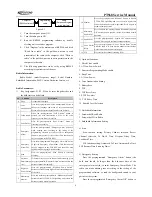
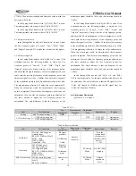
Table 6.5 Transmitter Section
Item
Test condition
Test
equipment
Measuring
terminal
Adjustment
parts
Requirement
Remark
Tx frequency
Frequency
counter /
General test set
PC Tuning
Mode
Within ±200Hz
DCS waveform
(balance)
Oscilloscope /
General test set
VR1
Smooth and
similar to square
wave
Power Power:
7.5V
Power meter/
General test set
Ammeter
PC Tuning
Mode
Adjust to 4W
Within
±0.2W
Max. modulation
deviation
CH
:
Tx center freq point
AG
:
1kHz/220mV
VR2
Adjust to ±4.2kHz
±200Hz
Modulation
sensitivity
CH
:
Tx center freq point
AG
:
1kHz/22mV
Deviation
meter/ General
test set
Deviation
checked should be
2.2kHz~3.6kHz
CTCSS DEV
CTCSS
:
67Hz
Deviation
meter/
General test
set
PC Tuning
Mode
Adjust to
±0.75kHz
±50Hz
DCS DEV
DCS
:
023N
Deviation
meter/
General test
set
PC Tuning
Mode
Adjust to
±0.75kHz
±50Hz
Low battery
warning
Battery terminal: 6.8V
Antenna
PC Tuning
Mode
Indicator flashes
after adjustment
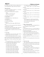
Chapter 7 Specifications
7.1
General Specifications
Product Model
PT568
136 ~ 174 MHz
400 ~ 450MHz
Frequency
420 ~ 470 MHz
Number of Channels
16
Channel Spacing
W: 25 kHz /N:12.5kHz
Operating Temperature -25
℃
~ +55
℃
Antenna Impedance
50
Ω
Frequency Stability
±2.5ppm
Battery (Standard
Configuration)
Li-Poly Battery: 1500mAH 7.4V
Dimension (W×H×D)
52.5mm × 111mm × 33.5mm
Weight
≤
270g: with antenna and 1500mAh
Li-Poly Battery
7.2 Receiver Section
Sensitivity (12dB SINAD)
0.25
μ
V(W) / 0.28
μ
V(N)
Adjacent Channel Selectivity
W:
≥
70dB / N:
≥
60dB
Intermodulation Interference
≥
65dB
Audio Output Power
1W (16
Ω
)
Audio Distortion
≤
5%
7.3 Transmitter Section
Tx Power
4W(UHF) / 5W(VHF)
Modulation Type
W:16K
φ
F3E / N:11K
φ
F3E
Clutter and Harmonic
≤
-36 dBm
Residual FM
(
300~3000Hz
)
W:
≤
-45 dB / N:
≤
-40dB
Audio Distortion
(
300~3000Hz
)
≤
5%
Adjacent Channel Power
W:
≥
70dB / N:
≥
60dB
Max. Deviation
W: <±5kHz / N: <±2.5kHz
Chapter 8 Troubleshooting
No.
Problem
Causes and Solutions
1 No display after
switching on
the radio
A. Battery power may be insufficient, please recharge
or change the battery pack.
B. The power switch is broken, please change it.
C. The CPU is broken, please change the IC.
D. The regulator tube IC12 is broken, please change
the IC.
2 PLL
unlocked
(Beeping)
A. The PLL crystal oscillator X4 is broken. Please
change it.
B. The oscillator transistor Q14 and Q15 are broken.
Please change them.
C. The PLL IC1 is broken. Please change it.
3
Cannot talk to
or hear other
A. The frequencies of both users are not the same,
select the same frequency channel.
Содержание PT568-01
Страница 26: ......
Страница 27: ......
Страница 28: ...PT568 Service Manual 28 Figure 5 PT568 Top Layer Position Value Diagram ...
Страница 29: ...PT568 Service Manual 29 Figure 6 PT568 Bottom Layer Position Value Diagram ...


