


PT568 Service Manual
12
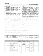
5.5 Exploded View
No.
Name
Part No.
PCS
1 PT568 Front Casing
201-000568-R02C
1
2 PT568 Light Guide
201-000568-R09A
1
3 PT568
Logo
401-0201E1-R97B
1
4 PT568 PTT Cover
201-000568-R05C
1
5 PT568 PTT Key
202-000568-R02A
1
6 PT568 Speaker Cover
201-000568-R03B
1
7 PT568 Metal Speaker Net
203-000568-R09C
1
8 PT568 Battery Hook 2
203-000568-R05C
1
9 PT568 Battery Hook 1
203-000568-R04C
1
10 PT568 Spring Sheet 2 for Battery Latch
203-000568-R07A
1
11 PT568 Spring Sheet 1 for Battery Latch
203-000568-R06A
1
12 PT568 Battery Latch
201-000568-R14A
1
13 M2.0*4.0 Screws
301-20040G-R01B
11
14 PT568 Mainboard
602-005682-R01
1
15 PT568 Al Alloy Chassis
203-000568-R02B
1
16 M2.0*8.0 Screws
301-20080G-R02B
2
17 PT568 Earphone Jack Bracket
201-000568-R11A
1
18 PT568 Main Waterproof Loop
202-000568-R01A
1
19 PT568 Bracket Waterproof Washer
202-000568-R05A
1
20 PT568 Battery Connector
201-000568-R13A
1
21 M2.5*8.0 Screws
301-25080J-R01
2
22 PT568 Top Cover
201-000568-R04B
1
23 PT558 Antenna Connector
203-000558-R07B
1
24 M2.0*4.0 Screws
301-20040G-R01B
2
25 PT558 Nut for Antenna
203-000558-R14A
1
26 PT558 Nut for Knob
203-000558-R13A
2
27 PT568 Volume Knob
201-000568-R06A
1
28 PT568 Channel Selector Knob
201-000568-R07A
1
29 PT568 Top Waterproof Gasket
202-000568-R04A
1
30 PT568 Top Gasket
203-000568-R08A
1
31 PT558 MIC Seal
202-000558-R09
1
32 Speaker
121-100000-R20
1
33 PT568 Earphone Jack Cover
201-000568-R10B
1
34 PT558 Waterproof Net for Speaker
204-000558-R01
1
35 PT568 Waterproof Gasket for MIC Head 204-000568-R01A
2
36 PT568 Emergency Button
202-000568-R03A
1
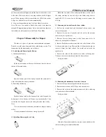
Chapter 6 Adjustment
Before test/adjustment, make sure all equipment has been well
connected to the ground!
Before test/adjustment, make sure the antenna output terminal
has been correctly connected to corresponding equipment or load!
The transmitter output terminal must be terminated with an RF
power attenuator and connected to a standard signal generator
(SSG)/frequency counter/deviation meter/spectrum analyzer
!
Make sure no transmission operation is being conducted while
measuring the receiver!
During the adjustment/test/maintenance, make sure reliable
anti-static measures are taken for human body and equipment.
6.1 Equipment and Software Required for Test and
Adjustment
Equipment and software listed in Table 6.1 are required for
test and adjustment of PT568.
Table 6.1 Equipment and Software Required for Test and
Adjustment
No.
Item
Specifications
1
Computer
P2 or above, IBM compatible PC,
WINDOWS 98/ME/2000/XP Operating
System
2
Programming software
KSP568
3
Programming cable
4
Clone cable
KCL01
5
DC regulated power supply
Output voltage: 7.5V
Output current:
≥
5A
6
RF power meter
Measurement range: 0.5-10W
Frequency range: 100MHz-500MHz
Impedance: 50
Ω
SWR
≤
1.2
7
Frequency counter
Frequency range: 0.1 - 600MHz
Frequency accuracy: better than ±1×10
-6
Sensitivity: better than 100mV
8
Deviation meter
Frequency range: DC - 600MHz
Measurement range: 0 - ±5kHz
9
DMM
Input impedance: above 10M
Ω
/V DC,
capable of measuring voltage, current and
resistance.
10 Audio signal generator
Frequency range:2-3000Hz
Output level: 1-500mV
11 RF power attenuator
Attenuation: 40dB or 50dB
Supporting power : higher than 10W
12 Standard signal generator
Frequency range: 10MHz-1000MHz
Output level:
0.1uV-32mV (-127dBm~-17dBm)
13 Oscilloscope
Frequency range: DC~20MHz
Test range: 10mV-20V
14 Audio frequency voltmeter Test range: 10mV-10V
Recommendation: Item 6, 7, 8, 10, 11, and 12 listed in the
table can be replaced by HP8920 general test set.
Содержание PT568-01
Страница 26: ......
Страница 27: ......
Страница 28: ...PT568 Service Manual 28 Figure 5 PT568 Top Layer Position Value Diagram ...
Страница 29: ...PT568 Service Manual 29 Figure 6 PT568 Bottom Layer Position Value Diagram ...