


PT568 Service Manual
14
0.75kHz. Then click narrowband, and adjust the value to make the
deviation at 0.35kHz.
In the Tuning Mode, double click “QT(151.4) DEV” to enter.
The tuning method is the same as that of “QT(67.0) DEV”.
In the Tuning Mode, double click “QT(254.1) DEV” to enter.
The tuning method is the same as that of “QT(67.0) DEV”.
6.3.8 Receiver Sensitivity
In the Tuning Mode, double click “Sensitivity” to enter. Adjust
the five frequency points of “Lowest”, “Low”, “Mid”, “High”,
and “Highest” among 0-255 to make the sensitivity be the highest.
6.3.9 Receiver Squelch
In the Tuning Mode, double click “SQL9 On” to enter. Click
wideband and use the following method to adjust the five
frequency points of “Lowest”, “Low”, “Mid”, “High”, and
“Highest” respectively. Firstly, click one of the frequency points,
and adjust the RF signal frequency of the test equipment to be the
same with the receiving frequency of that frequency point, and
adjust the signal level to be -116dBm. Then adjust the frequency
of the modulation signal to be 1kHz and the deviation to be 3kHz.
The programming software will adjust the value automatically.
When the value keeps stable, the adjustment of that frequency
point is completed. Then click the next frequency point to do the
adjustment. After all of the five frequency points are adjusted, use
the same method to adjust the five frequency points for
narrowband. The only difference is that the frequency of the
modulation signal should be 1kHz, and the deviation should be
1.5kHz.
In the Tuning Mode, double click “SQL9 Off” to enter. Click
wideband and use the following method to adjust the five
frequency points of “Lowest”, “Low”, “Mid”, “High”, and
“Highest” respectively. Firstly, click one of the frequency points,
and adjust the RF signal frequency of the test equipment to be the
same with the receiving frequency of that frequency point, and
adjust the signal level to be -118dBm. Then adjust the frequency
of the modulation signal to be 1kHz and the deviation to be 3kHz.
The programming software will adjust the value automatically.
When the value keeps stable, the adjustment of that frequency
point is completed. Then click the next frequency point to do the
adjustment. After all of the five frequency points are adjusted, use
the same method to adjust the five frequency points for
narrowband. The only difference is that the frequency of the
modulation signal should be 1kHz, and the deviation should be
1.5kHz.
In the Tuning Mode, double click “SQL1 On” and “SQL1
Off” to enter respectively. Use the same method stated above to do
the adjustment. The only difference is that the RF signal level for
“SQL1 On” should be 123dBm, and the RF signal level for
“SQL1 Off” should be 125dBm.
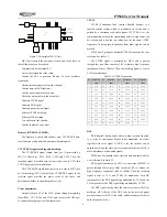
6.4 Adjustment Description
See Table 6.3, 6.4, and 6.5.
Table 6.3 VCO
Item
Test Condition
Test
Equipment
Measurement
Terminal
Adjustment
Parts
Requirement
Remark
Setting
BATT terminal voltage: 7.5V
DMM
CV
CH: Rx high freq point
C180
4.0V±0.2V
Adjustment
VCO lock voltage
CH: Tx high freq point
4.0V±0.2V
Adjustment
Table 6.4 Receiver Section
Item
Test Condition
Test
Equipment
Measurement
Terminal
Adjustment
Parts
Requirement
Remark
Audio level
Test freq: Mid freq point
Antenna input:
RF OUT: -53dBm (501
μ
V)
MOD:
1kHz
DEV: ±3.0kHz
Audio load: 16
Ω
(Turn the
volume knob
clockwise to
the end) Audio
power
>
1.2W
Sensitivity
CH: Mid freq point
CH: Low freq point
CH: High freq point
RF OUT: -119dBm (0.25
μ
V)
MOD: 1kHz
DEV: ±3.0kHz
PC Tuning
Mode
SINAD: 12dB
or higher
CH: Rx center freq point
SQL On sensitivity
Level 9
RF OUT: -116dBm
RF signal
generator
Oscilloscope
Audio
frequency
voltmeter
Distortion
meter
/General test
set
Speaker
connector
PC Tuning
Mode
Normal
squelch on
after
Содержание PT568-01
Страница 26: ......
Страница 27: ......
Страница 28: ...PT568 Service Manual 28 Figure 5 PT568 Top Layer Position Value Diagram ...
Страница 29: ...PT568 Service Manual 29 Figure 6 PT568 Bottom Layer Position Value Diagram ...


