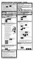
To get the control unit, open the fascia lifting the cover and
loosening the screw (
A
).
Pass the cables through
zone B
.
Carry out the cabling according to the diagram below.
The connections must be made exclusively by
qualified personnel when the voltage is off.
!
ELECTRICAL CONNECTIONS
CONNECTION DIAGRAM
Press button
P2/RAD
for
2 seconds
(the green
LED comes on)
Press button
P2/RAD
for
2 seconds
(the green
LED comes on)
Make a transmission
pressing the desired key
on the transmitter.
During entry, the green
LED flashes and then
remains steady on once
the code is memorised.
Power up the control
unit and put
DIP 1
on
OFF
Check that the control units is not set to operate with the dead man's switch (DIPs 2 and 3 must not both be OFF).
Using this procedure the installer can switch on the courtesy light independently with a radio remote control key (different from
the one selected in the previous paragraph for opening and door).
Memorise all the
transmitters making a
transmission with the
desired key.
At the end of the
operation, press button
P2/RAD
again to exit
the procedure.
(green LED goes off)
Make a transmission
pressing the desired
key on the
transmitter.
During entry, the green
LED flashes and then
remains steady on once
the code is stored.
Power up the control
unit and put
Dip 1
on
ON
Memorise all the
transmitters making a
transmission with the
desired key.
At the end of the
operation, press button
P2/RAD
again to exit
the procedure.
(green LED goes off)
Using this procedure the installer can delete all the previously programmed radio remote controls from the memory.
!
The programming procedures are exited automatically in any case 10 seconds after the last transmission.
!
PROGRAMMING THE RADIO REMOTE CONTROLS
PROGRAMMING THE CHANNEL FOR ACTIVATING THE AUTOMATION
PROGRAMMING THE CHANNEL FOR ACTIVATING THE COURTESY LIGHT
DELETING ALL THE CODES
Press button
P2/RAD
again within
6 seconds to confirm the deletion
(deletion is confirmed by the flashing
becoming faster)
Hold down button
P2/RAD
for
3 seconds
(the green LED
begins to flash rapidly)
B
A
21
22
GB
Safety devices in opening contact PHO2
STOP contact
Terminals 2, 4 common
START contact
12 Vdc power supply
Safety autotest (12Vdc)
Terminals 1, 8 common
Safety devices in closing contact PHO1
24Vdc power supply
FLASHING LAMP negative (0 V max 15W)
ANTENNA signal
ANTENNA sock
ON
1
2
3
4
[1]
[2]
[3]
[4]
[5]
[6]
[7]
[8]
[9]
[10]
230Vac power supply
Ground
230Vac power supply
[11]
[12]
[13]
[14]
[15]
CLOSING PHOTOCELL
CONNECTION
PHOTOCELL CONNECTION - “VIKY30” VERSION
OPENING PHOTOCELL
CONNECTION
+
9 7
8
9
7
RX
TX
NO
NC
C
-
+ -
+
9
7
1
9
7
RX
TX
NO
NC
C
-
+ -
Содержание Rolls 1200
Страница 2: ...1 3 5 2 4 6 F F B A E B C D E E H G 01...
Страница 3: ...7 9 11 8 10 12 I I I L B O O M M N N M M M M N N E A A 02...
Страница 4: ...13 14 15 16 17 18 H O P R Q 11 10 09 08 07 06 05 04 03 02 01 03...
Страница 5: ...19 20 R 04 22 21 24 23...
Страница 66: ......
Страница 67: ......


