background image

Page 7

Fig. 7

IMPORTANT!  The dome unit MUST be mounted to the air ride cab: NEVER to

any structure mounted directly to the frame.

4. Place dome unit on installation location chosen using the criteria discussed in the

previous section.  Shipping restraints must be removed 

(Fig. 5, Page 5)

, and cable

connection must be positioned facing rear of vehicle.

5. The dome unit must be positioned so that both feet on each side of the vehicle are equal

distances from the roof edge.  This should be checked by measuring the distance from
each foot to the roof edge.  Confirm that these measurements are equal. 

(Fig. 8)

IMPORTANT!  Make sure shipping restraints are removed from bottom of dome unit. 

(Fig. 5, Page 5)

Cable connection must ALWAYS be positioned facing the rear of vehicle.

Fig. 8

DOME INSTALLATION

IMPORTANT!  The dome should never be mounted so that it is

tilted more than two degrees in any direction.

Example of truck installation using bracket.  See bracket instructions for proper installation.

Содержание Trac-King In-Motion 9760

Страница 1: ...Installation and Operating Instructions 11200 Hampshire Avenue South Bloomington MN 55438 2453 Phone 800 982 9920 Fax 952 922 8424 www kingcontrols com 1355 REV C Satellite Solutions for Mobile Markets K KI IN NG G C CO ON NT TR RO OL LS S Trac King ...

Страница 2: ...ECTV division of GM Hughes Electronics Corporation Dish Network is an official trademark of Echostar Communications Corporation Bell ExpressVu is an official trademark of Bell Canada DVB is a trademark of the DVB Digital Video Broadcast Project 1991 1996 ELECTRICAL HAZARD WARNING The coaxial cable that connects the dome unit to the tuner carries a 30 volt electrical current Exercise extreme cautio...

Страница 3: ...m and access programming and diagnostic information Tuner Located in the vehicle Decodes the satellite signal so the Trac King locks onto the correct satellite Power Supply Located in the vehicle Supplies proper operating voltage to the Trac King SECTION 1 INTRODUCTION Note A TV satellite receiver and program subscription are also required for satellite TV viewing Not supplied by King Controls Fig...

Страница 4: ...ike a clock face front of vehicle is 12 00 rear is 6 00 Fig 2 SIGNAL STRENGTH Intensity of electronic signal received from the satellite transmission SECTION 2 DEFINITION OF TERMS Fig 2 Fig 3 ELEVATION Angle in degrees measured from the ground plane Fig 3 ...

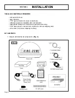
Страница 5: ...nch channel lock or pliers to remove shipping bolt wire cutter to remove shipping tie strap KIT CONTENTS 1 Unpack and identify all components Fig 4 KING DOME QUICK REFERENCE CARD The Trac King has a variety of options settings and information availabe via its display module Please review your owner s manual for a more detailed explanation the display module is used to provide the system current st...

Страница 6: ...ion DO NOT REMOVE THE DOME COVER TO REMOVE THESE SHIPPING RESTRAINTS 2 Remove and discard the tie strap bolt and plastic spacers that pass through the bottom of the base Fig 5 IMPORTANT Remove and discard Bolt and Plastic Spacer prior to installation IMPORTANT Remove and discard Tie Strap and Plastic Spacer prior to installation ...

Страница 7: ... the vehicle side to side c There must be no line of sight obstructions from this location Air conditioning units other antennas and storage areas that are too close to the dome unit may prevent the satellite signal from reaching the dish Fig 6 HEIGHT OF OBSTRUCTION APPROXIMATE MINIMUM DISTANCE TO DOME EDGE 10 8 11 10 12 12 13 14 14 16 15 18 16 20 Fig 6 IMPORTANT For installations on trucks with a...

Страница 8: ...both feet on each side of the vehicle are equal distances from the roof edge This should be checked by measuring the distance from each foot to the roof edge Confirm that these measurements are equal Fig 8 IMPORTANT Make sure shipping restraints are removed from bottom of dome unit Fig 5 Page 5 Cable connection must ALWAYS be positioned facing the rear of vehicle Fig 8 DOME INSTALLATION IMPORTANT ...

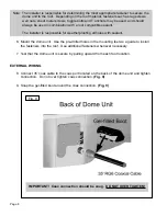
Страница 9: ...herproofing all holes with sealant 6 Mount the dome unit Use the pre drilled holes in the mounting feet as a guide to install the fasteners into the roof Use additional fasteners whenever necessary 7 Test that the dome unit is secure by pulling upward from each foot location EXTERNAL WIRING 8 Connect 35 coax cable to the coax port located on the back of the dome unit and tighten connection Do not ...

Страница 10: ...ole through the roof and into the cabinet where receiver is stored Feed coax down through hole Seal opening with roof compatible sealant so that it is entirely waterproof inside and outside of the 1 2 hole Fig 10 12 Remove blue protective sheet and red position to rear sticker from the dome unit Fig 10 TYPICAL ROOF INSTALLATION OVERHEAD VIEW IMPORTANT Sealant must be roof compatible ...

Страница 11: ...iver and accessible for operation and maintenance purposes b The Tuner should not be stacked directly on top of other electronics c The Controller should be conveniently located for the end user d All components should be secured so they do not shift or bounce around during vehicle motion SINGLE LNB Fig 11 For dual LNB hook up see Pages 12 13 1 Connect the 35 coax cable from the dome unit to the t...

Страница 12: ...Page 11 SINGLE LNB HOOK UP Fig 11 IMPORTANT AVOID SHARP BENDS WHEN ROUTING COAX ...

Страница 13: ...ly cable to the tuner port labeled PWR 6 Plug the power supply into a 110 VAC source Note The controller should turn on for 3 seconds and then turn off If the controller stays on press the ENTER and button simultaneously for 3 seconds to turn unit off ELECTRICAL HAZARD WARNING The coaxial cable that connects the dome unit to the tuner carries a 30 volt electrical current Exercise extreme caution w...

Страница 14: ...Page 13 DUAL LNB HOOK UP Fig 12 IMPORTANT AVOID SHARP BENDS WHEN ROUTING COAX ...

Страница 15: ...from reaching the dish SECTION 4 OPERATION 2 Press Trac King powers up performs a self diagnostic and loads software Trac King begins searching for indicated satellite in the indicated region Trac King has locked onto indicated satellite in indicated region ON POWERING UP PLEASE WAIT LOADING PLEASE WAIT RUN SCAN ALIGN NOW ON RUN SCAN ALIGN 2 NORTH CENTRAL RUN SCAN ALIGN DTV 101 RUN LOCKED S XX NOW...

Страница 16: ... buttons to display your region on the controller Sets REGION in memory Unit searches based on new REGION REGION OPTIONS 1 NORTH WEST 2 NORTH CENTRAL 3 NORTH EAST 4 CENTRAL WEST 5 MIDDLE CENTRAL 6 CENTRAL EAST 7 SOUTH WEST 8 SOUTH CENTRAL 9 SOUTH EAST ALL REGIONS 0 RECALIBRATE IDLE HOLD USER SETUP rev xxxx sn xxxxx SET REGION XXXXXXXXXXXX Display your region on the controller IDLE HOLD RUN SCAN AL...

Страница 17: ...h between satellites DTV 101 119 based on the channel or programming that you select on the Satellite Receiver multi satellite capable receiver is required Please keep in mind that the programming may pause freeze frame or pixelate while the antenna acquires and locks onto the new satellite The multiple satellite setting will work only if your satellite receiver is set up to work in oval dish mode...

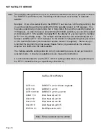
Страница 18: ...SET SATELLITE Display desired satellite on controller RUN SWITCHING Note The Trac King must remain turned on to maintain a signal If you are going to be stationary and wish to continue watching TV do not turn the system off Press ON to put the system into IDLE HOLD mode In IDLE HOLD mode the system cannot track the satellite when the vehicle is in motion Before moving the vehicle press ON to put t...

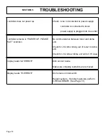
Страница 19: ...ads AZ ERROR Dish cannot rotate Make sure shipping restraints are removed Controller remains in POWER UP PLEASE WAIT condition No communication between tuner and dome unit Check for 24 volts coming out of tuner to dome unit Check for 24 volts at dome unit end of 35 coax Display reads EL ERROR Dish stuck on limit switch Restart system If problem persists perform 0 RECALIBRATE See Page 19 ...

Страница 20: ... dispaly shows Option 0 then press MAIN to return to main page 8 Press ENTER and simultaneously to shut system off 9 Unplug data cable from controller for 10 seconds and then plug back in 10 Wait until controller shows off then press ON to start system 11 Press ON to enter IDLE HOLD mode 12 Press MAIN to enter USER SETUP menu 13 Press to enter SET REGION menu 14 Press 5 times to scroll down to 0 R...

Страница 21: ...ild soap and water is recommended If you plan on storing your vehicle for long periods of time it is recommended that the system be put through a search procedure on a quarterly basis to keep all moving parts in good working order If you have any comments or questions please contact the King Controls Service Department at 1 800 982 9920 or email King Controls at info kingcontrols com SECTION 6 MAI...

Страница 22: ...en made or attempted by others that are not certified by King Controls to do such repairs Repairs are required because of normal wear and tear Alterations have been made to the product Unit has been sold by original owner In no event shall King Controls be liable for any indirect incidental or consequential damages from the sale or use of the product This disclaimer applies both during and after t...

Отзывы: