


CENTAURI ENERGY SERVER
User Manual - Model 30-2017/12/18-VERSION 1.0
12
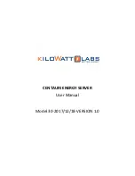
1.5.4 Introduction to Line Bank
R
S
T
N
R
S
T
N
R
S
T
AC INPUT
BYPASS INPUT
AC OUTPUT
+
-
+
-
+
-
+
-
PV INPUT 4#
PV INPUT 3#
PV INPUT 2#
PV INPUT 1#
BAT +
BAT –
Signs
Functions
PV INPUT 1#
PV 1 # input terminals "+"/ "-" pole
PV INPUT 2#
PV 2 # input terminals "+"/ "-" pole
PV INPUT 3#
PV 3 # input terminals "+"/ "-" pole
PV INPUT 4#
PV 4 # input terminals "+"/ "-" pole "
AC INPUT
"R" line, "S" line and "T" line of rectifier input terminal
BYPASS INPUT
"R" line, "S" line and "T" line of bypass input terminal
AC OUTPUT
"R" line, "S" line, "T" line an "N" line of system output terminal
BAT +
BAT input terminals "+" pole
BAT-
BAT input terminals "-"pole
Table 8 Description of Input Air Switch
1.5.5 Description of Remote Control Signal Input
Signs
Name
Control
method
Description of System Action
Battery
The battery temperature coefficient is
BAT TEMP
temperature
Sensing
used for the charge compensation.
BAT TEST
Battery self-Check
The system performs the battery test.
The system boots in the standby mode by
INV ON
System ON
pressing this sign.
The short circuit
The system shuts down in the ON mode by
INV OFF
System OFF
time is no less than
pressing this sign.
0.2s
Press this button to clear executed
abnormal protection command, the
FAULT CLEAR
Clear faults
system to will restart and run.
The system responses EPO command and
EPO
Emergency stop
output is interrupted.
Table 9 Description of Remote Control Signal Input
1.5.6
Description of Output Signal at System Dry Contact
English Name
Chinese name
Normally closed nodes Normally opened
nodes
FAN FAULT
Fan fault
Fan normal
Fan fault
SYS ALARM
System alarm
No system alarm
System alarm
GENERATOR ON/OFF
Generator ON/OFF
Generator OFF
The generator is on
Battery LOW
Battery low voltage
No low voltage alarm
Battery low voltage
for battery
OVERLOAD
Output overload
Output normal
Output overload


