A
Page 25 / 28
Datasheet 1.10-65.020-01-EN
RPW301-FTL
Product Description
Issue 2017-12-20 from V3.02
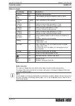
Status messages
Radio connection
The “Antenna” displays the current state of the radio connections to the radio partners.
The status of the radio connection is monitored continuously. A message is displayed if the radio
connection status changes.
NOTE
Communication is continued automatically once the radio connection between the room sensor and
the valve controllers is functioning properly again. “Δ1” or “Δ2” disappears and the “Antenna” icon
permanently appears.
Icon/display
State
Explanation
Antenna
On
Fault-free radio connection
Δ
InSt
On
“Test installation location” evaluation function is active
Antenna
Prog
Flashes
On
Valve controllers can be registered
Antenna
Δ1, Er01
On
On
Radio connection partly interrupted (> 1 hour)
At least one valve controller is being received
Antenna
Δ1, Er01
Off
On
Radio connection interrupted (> 1 hour)
No valve controller is being received
Antenna
Δ2, Er02
On
On
Radio connection partly interrupted (> 4 hours)
At least one valve controller is being received
Antenna
Δ2, Er02
Off
On
Initial registration failed or radio connection interrupted (> 4
hours)
No valve controllers are transmitting
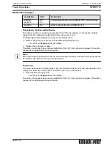
Battery
On
Room sensor
Charge state < 30%
ΔE, Er04
On
Valve controllers (1 to 4), for at least one valve controller
Charge state < 30%
On the service level, the battery icon also appears next to
each actuator.
Window
On
Economy mode for max. 30 minutes
U
On
Vacation mode activated (starts at 0.00)
On
Extended absence, vacation mode active
Sun
On
Off
Summer mode
System in energy saving mode


