background image

Setup Options

3

Keysight U1731C/U1732C/U1733C User’s Guide

79

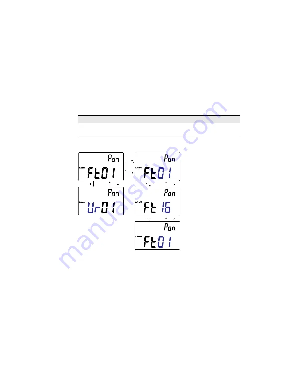
Changing the power-on limit category and set

This setting is used with the Limit comparison function (

page 58

). There are 32 

limit sets available (16 fixed factory sets, and 16 variable user sets). 
Use this Setup item to change the default category (factory or user) and set (1 to 

16) for subsequent power cycles.

Figure 3-8

Changing the power-on limit and category set

Parameter

Range

Default setting

Pon

– Factory (Ft01 to Ft16) or 
– User (Ur01 to Ur16)

Ft01

Press

Press

Press

Press

Press

Press

Press

Press

Содержание U1731C

Страница 1: ...Keysight U1731C U1732C U1733C Handheld LCR Meter User s Guide ...

Страница 2: ...ghts customarily provided to the public to use modify reproduce release per form display or disclose commercial computer software or commercial com puter software documentation No additional government requirements beyond those set forth in the EULA shall apply except to the extent that those terms rights or licenses are explicitly required from all providers of commercial computer software pursu ...

Страница 3: ... supply Both direct and alternating current Caution risk of electric shock Three phase alternating current Caution risk of danger refer to this manual for specific Warning or Caution information Earth ground terminal Caution hot surface Protective conductor terminal Out position of a bi stable push control Frame or chassis terminal In position of a bi stable push control Equipotentiality Equipment...

Страница 4: ...irements CAUTION Disconnect circuit power and discharge all high voltage capacitors before testing When measuring in circuit components first de energize the circuits before connecting them to the test leads This device is for indoor use at altitudes of up to 2000 m Always use the specified battery type listed in Characteristics and Specifications on page 89 The power for the meter is supplied wit...

Страница 5: ...ronments Never use the meter in wet conditions or when there is water on the surface If the meter is wet ensure that the meter is dried only by trained personnel When servicing the meter use only the specified replacement parts When using the probes keep your fingers behind the finger guards on the probes Connect the common test lead before you connect the live test lead When you disconnect the le...

Страница 6: ...l accuracy from 10 C to 55 C Operating humidity Full accuracy up to 80 RH relative humidity Storage temperature 20 C to 70 C Storage humidity 0 to 80 RH non condensing Altitude Up to 2000 meters Pollution degree Pollution degree II NOTE The U1731C U1732C U1733C Handheld LCR Meter complies with the following safety and EMC requirements IEC61010 1 2001 EN61010 1 2001 Second Edition IEC 61326 1 2005 ...

Страница 7: ...icates that this ISM device complies with the Canadian ICES 001 Cet appareil ISM est conforme a la norme NMB 001 du Canada This instrument complies with the WEEE Directive 2002 96 EC marking requirement This affixed product label indicates that you must not discard this electrical or electronic product in domestic household waste This symbol indicates the time period during which no hazardous or t...

Страница 8: ... a Monitoring and Control Instrument product The affixed product label is as shown below Do not dispose in domestic household waste To return this unwanted instrument contact your nearest Keysight Service Center or visit http about keysight com en companyinfo environment takeback shtml for more information Sales and Technical Support To contact Keysight for sales and technical support refer to the...

Страница 9: ...Support 8 1 Introduction About This Manual 18 Documentation map 18 Safety notes 18 Preparing Your LCR Meter 19 Check the shipment 19 Install the battery 19 Turn on your LCR meter 21 Automatic Power Off APO 22 Enabling the backlight 22 Selecting the range 23 Adjusting the tilt stand 24 Connecting the IR USB cable 25 Power on options 26 Your LCR Meter in Brief 27 Dimensions 27 Overview 29 Keypad 31 ...

Страница 10: ...l Features 56 Freezing the display Hold 56 Enabling the static recording mode Rec 56 Setting the high low limit comparison Limit 58 Making relative measurements Null 61 Performing the open short CAL 62 3 Setup Options Using the Setup Menu 66 Editing numerical values 67 Setup Menu Summary 68 Setup Menu Items 70 Changing the initial power on behavior 70 Changing the Ai function s phase angle conditi...

Страница 11: ...Keysight U1731C U1732C U1733C User s Guide 11 Resetting the Setup items 88 4 Characteristics and Specifications ...

Страница 12: ...12 Keysight U1731C U1732C U1733C User s Guide THIS PAGE HAS BEEN INTENTIONALLY LEFT BLANK ...

Страница 13: ... Figure 2 8 Impedance measurement with theta 51 Figure 2 9 Measuring impedance 52 Figure 2 10 Component above setting tolerance 54 Figure 2 11 ESR measurement with theta 55 Figure 2 12 DCR measurement 55 Figure 2 13 Using the Hold function 56 Figure 2 14 Using the Rec function 57 Figure 2 15 Using the Limit function 59 Figure 2 16 High and low limit values 60 Figure 2 17 nGo and Go indications 60 ...

Страница 14: ...e angle condition 78 Figure 3 8 Changing the power on limit and category set 79 Figure 3 9 Changing the user high low limit values 81 Figure 3 10 Changing the baud rate 82 Figure 3 11 Changing the parity check 83 Figure 3 12 Changing the data bits 84 Figure 3 13 Changing the beep frequency 85 Figure 3 14 Locking the push buttons 86 Figure 3 15 Changing the auto power off and backlight time outs 87...

Страница 15: ...entification phase angle rules 43 Table 2 2 Auto identification series parallel rules for resistance measurements 43 Table 2 3 Auto identification series parallel rules for capacitance measurements 44 Table 2 4 Auto identification series parallel rules for inductance measurements 44 Table 2 5 Available test frequencies 53 Table 2 6 Factory default high and low limit values 58 Table 3 1 Setup menu ...

Страница 16: ...16 Keysight U1731C U1732C U1733C User s Guide THIS PAGE HAS BEEN INTENTIONALLY LEFT BLANK ...

Страница 17: ...troduction About This Manual 18 Preparing Your LCR Meter 19 Your LCR Meter in Brief 27 Cleaning Your LCR Meter 39 This chapter teaches you how to set up your LCR meter for the first time An introduction to all the features and capabilities of the LCR meter is also given ...

Страница 18: ... Check the manual revision on the first page of each manual User s Guide This manual Quick Start Guide Printed copy for outdoor use included with shipment Keysight GUI Data Logger Software Quick Start Guide and Help Free download at the Keysight website Safety notes Safety notes are used throughout this manual see the Safety Information section for format examples Familiarize yourself with each of...

Страница 19: ...ccessories and your ordered options are included in the shipment according to the standard shipped items list found in the printed copy of the U1731C U1732C U1733C Quick Start Guide 3 For any question or problems refer to the Keysight contact numbers on the back of this manual Install the battery Your LCR meter is powered by a single 9 V alkaline battery included with the shipment When you receive...

Страница 20: ...ttery cover Place the battery cover back in its original position and tighten the screw Figure 1 1 Installing the batteries The battery level indicator in the lower right hand corner of the display indicates the relative condition of the battery Table 1 1 describes the various battery levels the indicator represents WARNING To avoid false readings which could lead to possible electric shock or per...

Страница 21: ...tton CAUTION To avoid instruments being damage from battery leakage Always remove dead batteries immediately Always remove the battery and store it separately if the LCR meter is not going to be used for a long period Table 1 1 Battery level indicator Indication Battery capacity Full capacity 2 3 capacity 1 3 capacity Flashing periodically Almost empty less than one day 1 1 Battery change advised ...

Страница 22: ...ve battery life a user adjustable time out controls how long the backlight stays on The default time out is 30 seconds NOTE You can change the power on behavior of your LCR meter for subsequent power cycles See Changing the initial power on behavior on page 70 for more information on changing the LCR meter s power on setting NOTE To change the time out period or completely disable the APO function...

Страница 23: ... better performance since the LCR meter does not have to determine which range to use for each measurement In autorange the LCR meter selects the lowest range to display the highest available precision resolution for the input signal If manual range is already enabled press for more than 1 second to enter the autoranging mode If autoranging is enabled press to enter the manual range mode Each addi...

Страница 24: ...C U1732C U1733C User s Guide Adjusting the tilt stand To adjust the LCR meter to a 60 standing position pull the tilt stand outward to its maximum reach Figure 1 3 Tilt stand adjustment and IR cable connection To PC host IR USB cable ...

Страница 25: ...5481A IR USB cable purchased separately connected to the LCR meter is facing up Firmly push the IR head into the LCR meter s IR communication port until it snaps into place see Figure 1 3 Refer to the Keysight GUI Data Logger Software Quick Start Guide and Help for more information on the IR communication link and the Keysight GUI Data Logger software Figure 1 4 Keysight GUI Data Logger Software T...

Страница 26: ...any key to exit this mode Simulates the Auto Power Off APO mode Press any key to turn the LCR meter back on and resume normal operation Checks the firmware version The LCR meter s firmware version will be shown on the primary display Press any key to exit this mode Performs the Open Short CAL on all frequencies and all ranges for the User mode 1 Enters the Setup menu See Chapter 3 Setup Options st...

Страница 27: ...Introduction 1 Keysight U1731C U1732C U1733C User s Guide 27 Your LCR Meter in Brief Dimensions Front view Figure 1 5 Width dimensions 87 mm ...

Страница 28: ...1 Introduction 28 Keysight U1731C U1732C U1733C User s Guide Rear and side view Figure 1 6 Height and depth dimensions 184 mm 41 mm ...

Страница 29: ...s of your LCR meter are described in this section Click the respective Learn more pages in Table 1 3 for more information on each part Figure 1 7 Front panel 1 2 3 Table 1 3 Front panel parts Legend Description Learn more on 1 Display screen page 34 2 Keypad page 31 3 Input terminals and sockets page 38 ...

Страница 30: ...more pages in Table 1 4 for more information on each part Figure 1 8 Rear panel 1 2 3 4 Table 1 4 Rear panel parts Legend Description Learn more on 1 IR communication port page 25 2 Tilt stand page 24 3 Battery cover lift the tilt stand for access page 19 4 External power adapter input jack 1 1 The external power adapter input jack requires an input voltage of 12 VDC ...

Страница 31: ... or off page 21 Starts or stops the auto identification mode Press again while the annunciator is shown to exit this mode Enables or disables the ESR equivalent series resistance mode Press for more than 1 second to exit this mode The LCR meter will return to capacitance measurement by default page 42 Holds or releases the present reading on the display Press again to update the reading automatica...

Страница 32: ...again to cycle through the various test frequencies 100 Hz to 100 kHz U1733C only Enables or disables the DCR direct current resistance mode Press for more than 1 second to exit this mode The LCR meter will return to inductance measurement by default page 53 Disables autoranging and sets a manual range Press again to cycle through each available measurement range Enables autoranging page 23 Switch...

Страница 33: ...d backlight time outs on page 87 page 54 and page 22 Sets the null relative mode The displayed value is saved as a reference to be subtracted from subsequent measurements Press again to cancel the null mode Enters the open short calibration mode for the selected range and test frequency Follow the prompts on the screen open or short connector and press to begin the calibration process The LCR mete...

Страница 34: ... in Figure 1 7 is described in Table 1 6 Click the respective Learn more pages in Table 1 6 for more information on each annunciator Table 1 6 General annunciators Legend Description Learn more on Remote control via PC indicator page 25 Equivalent series resistance indicator Resistance measurement by direct current indicator LCR meter using open short CAL settings by factory page 62 LCR meter usin...

Страница 35: ...a hold mode indicator page 56 Audible alert indicator for tolerance or limit mode page 85 Dissipation factor indicator page 53 Quality factor indicator Phase angle of impedance indicator Secondary display Measurement units for the secondary display page 37 Impedance measurement indicator page 51 Inductance measurement indicator page 45 Capacitance measurement indicator page 47 Resistance measureme...

Страница 36: ...n primary display Relative Null indicator page 61 Autoranging indicator page 23 Limit mode indicator page 58 Reading out of HI limit Reading out of LO limit Auto power off indicator page 22 Primary display Measurement units for the primary display page 37 Parallel mode indicator page 53 Series mode indicator Battery capacity indicator page 21 Table 1 6 General annunciators continued Legend Descrip...

Страница 37: ...Table 1 7 Measurement units display Sign Notation Description M Mega 1E 06 1000000 k kilo 1E 03 1000 m milli 1E 03 0 001 μ micro 1E 06 0 000001 n nano 1E 09 0 000000001 p pico 1E 12 0 000000000001 Degree unit for phase angle measurement Percentage unit for tolerance measurement μH mH H Henry units for inductance measurement pF nF μF mF Farad units for capacitance measurement Ω kΩ MΩ Ohm units for ...

Страница 38: ...he table below WARNING To avoid damaging this instrument do not exceed the input limit Do not apply voltage to input terminals Discharge the capacitor before testing Table 1 8 Input terminal socket connections Input terminal socket Description Positive terminal component socket Negative terminal component socket Guard terminal component socket GUARD ...

Страница 39: ...ter off and remove the test leads 2 Turn the LCR meter over and shake out any dirt that may have accumulated in the terminals 3 Wipe the case with a damp cloth and mild detergent do not use abrasives or solvents 4 Wipe the contacts in each terminal with a clean swab dipped in alcohol WARNING To avoid electrical shock or damage to the LCR meter ensure that the insides of the casing stay dry at all ...

Страница 40: ...1 Introduction 40 Keysight U1731C U1732C U1733C User s Guide THIS PAGE HAS BEEN INTENTIONALLY LEFT BLANK ...

Страница 41: ... U1733C Handheld LCR Meter User s Guide 41 2 Features and Functions Making Measurements 42 Additional Features 56 This chapter provides detailed information on the features and functions that are available in your LCR meter ...

Страница 42: ...appropriate measurement in the primary display L C or R and secondary display D Q or θ selects an appropriate range and selects an appropriate measuring mode series or parallel NOTE The Ai function helps to identify L C and R measurements automatically according to the angle of impedance detected in the DUT See Table 2 1 for the phase angle rules The default phase angle condition is set to 10 You ...

Страница 43: ...tification phase angle rules Phase angle 1 Primary display Secondary display Set θ Set R θ θ Set L Q θ Set C D 1 Where Set is the phase angle selected Table 2 2 Auto identification series parallel rules for resistance measurements Resistance range Down range Up range 200 MΩ Parallel Parallel 20 MΩ Parallel Parallel 2000 kΩ Parallel Parallel 200 kΩ Parallel Parallel 20 kΩ Parallel Series 2000 Ω Par...

Страница 44: ...allel Parallel Series Parallel Series Parallel 200 pF Parallel Parallel Parallel Parallel Series Parallel 20 pF Parallel Parallel Parallel Parallel Table 2 4 Auto identification series parallel rules for inductance measurements Range 100 Hz 120 Hz 1 kHz 10 kHz 100 kHz Down Up Down Up Down Up Down Up Down Up 2000 H Parallel Parallel Parallel Parallel Parallel Parallel 200 H Parallel Parallel Parall...

Страница 45: ...ess to select inductance measurement Figure 2 2 Inductance measurement with Q factor 3 Insert an inductor into the component socket or connect the test clip to the component leads as required 4 Press to change the secondary display measurement D Q or θ 5 Read the displays NOTE It is recommended that you perform the Open Short calibration see page 62 before testing to achieve optimum precision for ...

Страница 46: ...2 Features and Functions 46 Keysight U1731C U1732C U1733C User s Guide Figure 2 3 Measuring inductance Inductor 3 2 OR Surface Mount Device SMD U1782B SMD Tweezers P S ZLCR Freq 1 OR 1 Freq ...

Страница 47: ... to enable the auto identification function or b alternatively press to select capacitance measurement Figure 2 4 Capacitance measurement with D factor 3 Insert a capacitor into the component socket or connect the test clip to the component leads as required 4 Press to change the secondary display measurement D Q or θ 5 Read the displays WARNING To avoid electrical hazards discharge the capacitor ...

Страница 48: ...2 Features and Functions 48 Keysight U1731C U1732C U1733C User s Guide Figure 2 5 Measuring capacitance 3 2 OR Surface Mount Device SMD U1782B SMD Tweezers Capacitor P S ZLCR Freq 1 OR 1 Freq ...

Страница 49: ...o enable the auto identification function or b alternatively press to select resistance measurement Figure 2 6 Resistance measurement 3 Insert a resistor into the component socket or connect the test clip to the component leads as required 4 Read the display CAUTION To avoid possible damage to your LCR meter or to the equipment under test disconnect the circuit power and discharge all high voltage...

Страница 50: ...2 Features and Functions 50 Keysight U1731C U1732C U1733C User s Guide Figure 2 7 Measuring resistance Resistor 3 2 OR Surface Mount Device SMD U1782B SMD Tweezers P S ZLCR Freq 1 OR 1 Freq ...

Страница 51: ...ure impedance as shown in Figure 2 9 1 Press to power on the LCR meter 2 Press to select a suitable test frequency and press to select impedance measurement Figure 2 8 Impedance measurement with theta 3 Insert a component into the component socket or connect the test clip to the component leads as required 4 Press to change the secondary display measurement D Q or θ 5 Read the displays NOTE To lea...

Страница 52: ...2 Features and Functions 52 Keysight U1731C U1732C U1733C User s Guide Figure 2 9 Measuring impedance 3 Device Under Test DUT 2 P S ZLCR Freq OR Surface Mount Device SMD U1782B SMD Tweezers 1 ...

Страница 53: ... kHz by default Press the key to select a desired test frequency Selecting parallel series circuit mode P S The LCR meter can display parallel or series mode data for all ranges Press the key for more than 1 second to toggle the parallel and series mode Series mode is set as the default setting You can however change this power on behavior in the Setup menu See Changing the initial power on behavi...

Страница 54: ... a standard value to sort components Press again to cycle through 1 5 10 and 20 tolerance as desired This function is designed for convenient component sorting The beeper will beep three times whenever the component under test exceeds the setting tolerance Conversely when the beeper beeps once this indicates that the component is within the setting tolerance Figure 2 10 Component above setting tol...

Страница 55: ...lent series resistance of the capacitor independent of its capacitance Figure 2 11 ESR measurement with theta Press for more than 1 second to exit this mode Enabling DCR measurements Press for more than 1 second to select the DCR measurement The DCR measurement measures the resistance of an unknown component by 1 VDC Figure 2 12 DCR measurement Press for more than 1 second to exit this mode Freq F...

Страница 56: ...flashes while waiting for the reading to be stable Press for more than 1 second to release the Hold function Enabling the static recording mode Rec The static recording mode stores the maximum minimum and average input values during a series of measurements in the LCR meter s memory When the input goes below the recorded minimum value or above the recorded maximum value the LCR meter beeps and rec...

Страница 57: ...e than 1 second to enter the static recording mode Figure 2 14 Using the Rec function Press again to cycle through the Max Min Avg or MaxMinAvg present input values To exit this mode press and hold the key for more than 1 second Rec Hold Rec Hold 1s Rec Hold Rec Hold NOTE Static recording captures only stable values and updates the memory it will not record any overload value for any of the LCR fu...

Страница 58: ... can set the LCR meter to use the user sets upon start up from the Setup menu See Changing the power on limit category and set on page 79 for more information Table 2 6 shows the factory default limit values for each set Table 2 6 Factory default high and low limit values Set High limit H Low limit L F01 1000 900 F02 1200 1080 F03 1500 1350 F04 1800 1620 F05 2200 1980 F06 2700 2430 F07 3300 2970 F...

Страница 59: ... secondary display Figure 2 15 Using the Limit function While the annunciator is flashing use the or key to select an appropriate limit set NOTE The default values of the variable user sets are set to the same as the fixed user sets Use the Setup menu to change the high and low limits for each set See Changing the user high low limit values on page 80 for more information Limit DQO Limit DQO 1s Fr...

Страница 60: ...fter 3 seconds the comparison will also begin The LCR meter beeps three times and displays in the secondary display if the reading is greater than the high limit or lesser than the low limit If the reading is within the high and low limits the meter beeps once and displays in the secondary display Figure 2 17 nGo and Go indications The limit set used in the comparison is displayed after the indica...

Страница 61: ...ssible application is to increase the accuracy of a resistance measurement by nulling the test lead resistance test leads shorted Nulling the leads is also particularly important prior to making capacitance measurements test leads open Press the key to enter the relative mode and store the display reading as a reference value The LCR meter will then display all subsequent readings relative to the ...

Страница 62: ...nd all ranges OS User Open Short CAL is performed at every power on option interval It covers all frequencies and all ranges see page 26 for the OS User setup Open Short CAL for single range and frequency by pressing and holding the key for more than 1 second The corrections for the and are pre stored in the LCR meter They are both calibrated at the terminal ends You can set the LCR meter to start...

Страница 63: ...he open short CAL function is available for fixed measurement ranges Figure 2 19 Using the Cal function Figure 2 20 Open calibration and short calibration prompts NOTE It is highly recommended that open short CAL be performed before making precision measurements Cal Null 1s ...

Страница 64: ...pen Short CAL prompts will be shown on the display Follow the prompts for open connector OPn or short connector SHor connection and press the key The CAL annunciator on the upper right of the display will flash indicating that the correction is in process 3 After the open short CAL is completed the LCR meter will be restored to the normal display and ready for normal usage Cal Null Cal Null ...

Страница 65: ...C U1732C U1733C Handheld LCR Meter User s Guide 65 3 Setup Options Using the Setup Menu 66 Setup Menu Summary 68 Setup Menu Items 70 The following chapter describes how to change the preset features of your LCR meter ...

Страница 66: ...etup menu key functions Legend Description Press and hold while turning the LCR meter ON to access the Setup menu Press and hold for more than 1 second to exit this mode Press or to step through the menu items Press or at each menu item to change the preset settings The menu item in the secondary display will flash to indicate that you can now change the menu item values Press or again to switch b...

Страница 67: ...t and Press to move the cursor to the right When the cursor is positioned over a digit use the and keys to change the numerical digit Press to increment the digit and Press to decrement the digit When you have completed your changes save the new numerical value by pressing Or alternatively if you wish to discard the changes you made press Limit DQO Auto Range Limit DQO Auto Range Freq Freq Rec Hol...

Страница 68: ...fault is quality factor Q and series S page 73 D Q or θ and P or S Set the capacitance C secondary parameter and measurement mode that the LCR meter powers up in Default is dissipation factor D and series S page 74 D Q or θ and P or S Set the resistance R secondary parameter and measurement mode that the LCR meter powers up in Default is phase angle θ and series S page 75 FACt or USEr Set the open...

Страница 69: ...Hz 4000 Hz or oFF Set the LCR meter s beep frequency 2000 Hz 3000 Hz 4000 Hz or off Default is 4000 Hz page 85 oFF or on Lock the LCR meter s push buttons Default is off page 86 01 to 99 mins or oFF Set the auto power off time out period from 1 to 99 minutes 1 hour 39 minutes or off Default is 5 minutes page 87 01 to 99 s or oFF Set the LCD backlight timeout period from 1 to 99 seconds 1 minute 39...

Страница 70: ...meter to start up in the auto identification mode Ai impedance measurement Z inductance measurement L capacitance measurement C resistance measurement R equivalent series resistance mode ESR or direct current resistance mode DCR for U1733C only Parameter Range Default setting Pon tYPE Ai Z L C R ESR or DCR Ai Pon FrEq 100 Hz 120 Hz 1 kHz 10 kHz or 100 kHz 1 kHz Pon AUto L D Q or θ Parallel or Seri...

Страница 71: ...eysight U1731C U1732C U1733C User s Guide 71 The LCR meter will start up in the selected measurement type for subsequent power cycles Figure 3 1 Changing the power on measurement type Press Press Press Press Press Press ...

Страница 72: ...s Setup item to change the LCR meter s initial test frequency You can set the LCR meter to start up using a test frequency from 100 Hz to 100 kHz The LCR meter will start up using the selected test frequency for subsequent power cycles Figure 3 2 Changing the power on test frequency Press Press Press Press ...

Страница 73: ...ent s initial secondary parameter dissipation factor D quality factor Q or phase angle θ and measurement mode parallel or series The inductance L measurement will start up using the selected secondary parameter and measurement mode for subsequent power cycles Figure 3 3 Changing the power on secondary parameter and measurement mode for inductance L measurements Press Press Press Press Press Press ...

Страница 74: ...ent s initial secondary parameter dissipation factor D quality factor Q or phase angle θ and measurement mode parallel or series The capacitance C measurement will start up using the selected secondary parameter and measurement mode for subsequent power cycles Figure 3 4 Changing the power on secondary parameter and measurement mode for capacitance C measurements Press Press Press Press Press Pres...

Страница 75: ...ent s initial secondary parameter dissipation factor D quality factor Q or phase angle θ and measurement mode parallel or series The resistance R measurement will start up using the selected secondary parameter and measurement mode for subsequent power cycles Figure 3 5 Changing the power on secondary parameter and measurement mode for resistance R measurements Press Press Press Press Press Press ...

Страница 76: ...t CAL Use this Setup item to change the LCR meter s initial open short CAL to either the factory open short CAL FACt or user open short CAL USEr The LCR meter will start up using the selected open short CAL for subsequent power cycles Figure 3 6 Changing the power on open short CAL Press Press ...

Страница 77: ...e angle of impedance detected in the DUT Use this Setup item to change the default phase angle for the Ai function between 5 and 45 Table 3 3 shows the correlation between the phase angle detected and the L C and R measurements selected Parameter Range Default setting Ai 5 to 45 10 Table 3 3 Auto identification phase angle rules Phase angle 1 Primary display Secondary display Set θ Set R θ θ Set L...

Страница 78: ...3 Setup Options 78 Keysight U1731C U1732C U1733C User s Guide Figure 3 7 Changing the Ai function s phase angle condition Press Press Press Press Press Press ...

Страница 79: ...re are 32 limit sets available 16 fixed factory sets and 16 variable user sets Use this Setup item to change the default category factory or user and set 1 to 16 for subsequent power cycles Figure 3 8 Changing the power on limit and category set Parameter Range Default setting Pon Factory Ft01 to Ft16 or User Ur01 to Ur16 Ft01 Press Press Press Press Press Press Press Press ...

Страница 80: ...lues for each set NOTE The low limit can be set from 0 to less than or equal to the high limit and the high limit can be set from more than or equal to the low limit to less than or equal to the maximum display count 19999 Parameter Range Default setting H 01 to 16 or L 01 to 16 0 to 19999 See Table 3 4 Table 3 4 Default user high low limit values Set High limit H Low limit L U01 1000 900 U02 1200...

Страница 81: ... high low limit values U12 8200 7380 U13 10000 9000 U14 12000 10800 U15 15000 13500 U16 18000 16200 Table 3 4 Default user high low limit values continued Set High limit H Low limit L Press Press Press Press Press Press Press Press Press Press Press Press Press Press Press Press Press Press ...

Страница 82: ...e IR communication link and the Keysight GUI Data Logger software to control your LCR meter remotely page 25 Use this Setup item to change the baud rate for remote communications with a PC Figure 3 10 Changing the baud rate Parameter Range Default setting bPS 9600 or 19200 bits second 9600 bits second Press Press ...

Страница 83: ...h the IR communication link and the Keysight GUI Data Logger software to control your LCR meter remotely page 25 Use this Setup item to change the parity check for remote communications with a PC Figure 3 11 Changing the parity check Parameter Range Default setting PAr nonE En or odd nonE Press Press Press Press ...

Страница 84: ...Keysight GUI Data Logger software to control your LCR meter remotely page 25 Use this Setup item to change the number of data bits data width for remote communications with a PC The number of the stop bit is always 1 and this cannot be changed Figure 3 12 Changing the data bits Parameter Range Default setting dAt 7 bit or 8 bit 8 bit Press Press ...

Страница 85: ...of newly sensed values for static recordings sensed values that are out of tolerance or limits set as well as invalid key operations Use this Setup item to change the driving frequency of the beeper Figure 3 13 Changing the beep frequency Parameter Range Default setting bEP 2000 3000 4000 Hz or oFF 4000 Hz Press Press Press Press Press Press ...

Страница 86: ...he push buttons keys of your LCR meter If enabled all keys will be locked rendered unoperational when you exit the Setup menu Unlock the push buttons again by entering the Setup menu through the power on options page 26 Figure 3 14 Locking the push buttons Parameter Range Default setting LPb on or oFF oFF Press Press ...

Страница 87: ... see page page 22 features use timers to determine when to turn off the backlight and when to automatically turn the LCR meter off Figure 3 15 Changing the auto power off and backlight time outs Parameter Range Default setting APo 01 to 99 minutes or oFF 05 minutes bLt 01 to 99 seconds or oFF 30 seconds Press Press Press Press Press Press Press Press Press Press Press Press ...

Страница 88: ...he Setup items can be reset to their default values through this Setup item Press to perform the reset The LCR meter will beep once exit the Setup menu and return to normal operation Figure 3 16 Resetting the Setup items Parameter Range Default setting rSt dEFA dEFA Rec Hold Press R ec Hold ...

Страница 89: ... LCR Meter User s Guide 89 4 Characteristics and Specifications For the characteristics and specifications of the U1731C U1732C U1733C Handheld LCR Meter refer to the datasheet at http literature cdn keysight com litweb pdf 5990 7778EN pdf ...

Страница 90: ...4 Characteristics and Specifications 90 Keysight U1731C U1732C U1733C User s Guide THIS PAGE HAS BEEN INTENTIONALLY LEFT BLANK ...

Страница 91: ...ion is subject to change without notice Always refer to the Keysight website for the latest revision Keysight Technologies 2011 2017 Edition 9 July 1 2017 Printed in Malaysia U1731 90077 U1731 90077 www keysight com ...

Отзывы: