Installation
2
Series N8700 User’s Guide
35
Setting the Over-Voltage Protection
The master unit OVP should be programmed to the desired OVP level.
The OVP of the slave units should be programmed to a
HIGHER
value than the master. When the master unit shuts down, it programs
the slave unit to zero output voltage. If a slave unit shuts down when
its OVP is set lower than the master output voltage, only that unit
shuts down and the remaining slave units will supply the entire load
current.
Setting the Over-Current Protection
Over-current protection, if desired,
may only be used with the
MASTER unit.
When the master unit shuts down, it programs the
slave units to zero output voltage.
Series Connections
WARNING
SHOCK HAZARD
For models up to 60 VDC rated output, no point on the output shall be more
than ±60 VDC above or below chassis ground.
For models greater than 60 VDC rated output, no point on the Positive output
shall be more than ±600 VDC above or below chassis ground.
For models greater than 60 VDC rated output, no point on the Negative output
shall be more than ±400 VDC above or below chassis ground.
CAUTION
Only power supplies that have identical voltage and current ratings can be
connected in series.
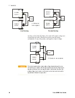
Two units of the same voltage and current rating can be connected in
series to provide up to two times the output voltage capability.
Because the current is the same through each element in a series
circuit, outputs connected in series must have equivalent current
ratings. Otherwise, the higher rated output could potentially damage
the lower rated output by forcing excessive current through it under
certain load conditions. Refer to the following figures for typical
series connections using either local or remote sensing.
It is recommended that diodes be connected in parallel with each
output to prevent reverse voltage during start up sequence or in case
one unit shuts down. Each diode should be rated to at least the rated
output voltage and output current of the power supply.


