background image

Appendix B


Verification and Calibration 

108 

Series N8700 User’s Guide 

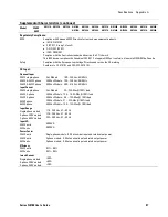
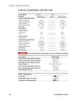
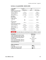
Test Record – Keysight N8732A   [10V, 330A, 3.3kW] 


Keysight N8732A 
Description 

Report No _______________ 

Date __________________ 

Minimum Specs. 

Results 

Maximum Specs. 

Voltage Programming & Readback 

  Minimum Voltage Vout  
  Measurement Readback 
  High Voltage Vout 
  Measurement Readback 


20 mV 

 Vout 

 10 mV 

9.990 V 

Vout 

 20 mV 


_____________ 
_____________ 
_____________ 
_____________ 


30 mV 

 Vout + 10 mV 

10.010 V 

Vout + 20 mV 

CV Load Effect 

 6.5 mV 

_____________ 

+ 6.5 mV 

CV Source Effect 

 3 mV 

_____________ 

+ 3 mV 

CV Ripple and Noise 

  peak-to-peak 
  rms 


N/A 
N/A 


_____________ 
_____________ 


60 mV 

8 mV 

Transient Response 

  Voltage @ 1 ms 


 50 mV 


_____________ 


+ 50 mV 

Current Programming & Readback 

  Minimum Current Iout  
  Measurement Readback 
  High Current Iout 
  Measurement Readback 


1.3 A 

Iout 

 990 mA 

329.01 A 

Iout 

 1.32 A 


_____________ 
_____________ 
_____________ 
_____________ 


2.6 A 

Iout + 990 mA 

330.99 A 

Iout + 1.32 A 

CC Load Effect 

 71 mA 

_____________ 

+ 71 mA 

CC Source Effect 

 35 mA 

_____________ 

+ 35 mA 


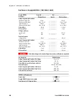
WARNING 

Return the voltage and current settings to zero when verification is completed 


Test Description 

N8732A Settings 

Voltage Programming & Readback, Min Voltage 

25 mV, 2A 

Voltage Programming & Readback, High Voltage 

10V, 2A 

CV Load Effect, Source Effect, Ripple and Noise 

10V, 330A 

Transient Response 

10V, from 33A to 297A 

Current Programming & Readback,  Min Current 

2A, 10V 

Current Programming & Readback, High Current 

330A, 10V 

CC Load Effect, Source Effect 

330A, 10V 


N8732A  Load Requirements 


Current shunt 

0.0005

W

 500 A 

Keysight N3300 Electronic load modules  

6 – N3306A 

Fixed Resistor for CV Ripple and Noise 

0.03

W

  3.5 kW 

Содержание N8700

Страница 1: ...User s Guide Keysight Series N8700 System DC Power Supply ...

Страница 2: ......

Страница 3: ......

Страница 4: ...uct Category With reference to the equipment types in the WEEE directive Annex 1 this product is classified as Monitoring and Control instrumentation product Do not dispose in domestic household waste To return unwanted products contact our local Keysight office or see www keysight com environment product for more information Certification Keysight Technologies certifies that this product met its ...

Страница 5: ...ed personnel who are aware of the hazards involved should remove instrument covers Always disconnect the power cable and any external circuits before removing the instrument cover Do Not Modify the Instrument Do not install substitute parts or perform any unauthorized modification to the product Return the product to a Keysight Sales and Service Office for service and repair to ensure that safety ...

Страница 6: ... SCPI command structure and basic programming concepts Language Reference Chapter 5 describes all of the SCPI programming commands Programming Examples Chapter 6 provides Visual BASIC example programs that illustrate some common applications Specifications Appendix A describes specifications and supplemental characteristics Verification and Calibration Procedures Appendix B explains the verificati...

Страница 7: ...ns 31 Parallel Connections 33 Series Connections 35 J1 Connector Connections 37 3 Operating the Power Supply Locally Turn On Check Out 40 Normal Operation 42 Protection Functions 43 Output On Off Controls 46 Analog Programming of Output Voltage and Current 49 4 Operating the Power Supply Remotely Connecting to the Interfaces 54 SCPI Commands an Introduction 63 5 Language Reference SCPI Command Sum...

Страница 8: ...pplemental Characteristics 95 Outline Diagram 98 Appendix B Verification and Calibration Verification 99 Calibration 128 Appendix C Service Types of Service Available 132 Repackaging for Shipment 132 Operating Checklist 132 Error Messages 134 Recycling Plastic Components 138 Appendix D Compatibility Differences In General 140 Compatibility Command Summary 141 Index 143 ...

Страница 9: ... N8700 Power Supplies This chapter is not meant to describe every operating feature in detail It is simply a quick reference guide to quickly become familiar with the essential components of the power supply It can also be used as a memory jogger for experienced users to quickly find a front rear panel function A quick reference programming command chart is included in the beginning of chapter 5 ...

Страница 10: ...The rear panel includes the necessary connectors to control and monitor the power supply operation by analog signals or by the built in remote communication interfaces Output Features Constant voltage constant current with automatic crossover High resolution voltage and current front panel controls Accurate voltage and current readback Independent edge triggered external shut off and level trigger...

Страница 11: ... kW Models Note 1 2 5 kW Models Note 1 2 Model Voltage Range Current Range Model Voltage Range Current Range N8731A 0 8V 0 400A N8754A 0 20V 0 250A N8732A 0 10V 0 330A N8755A 0 30V 0 170A N8733A 0 15V 0 220A N8756A 0 40V 0 125A N8734A 0 20V 0 165A N8757A 0 60V 0 85A N8735A 0 30V 0 110A N8758A 0 80V 0 65A N8736A 0 40V 0 85A N8759A 0 100V 0 50A N8737A 0 60V 0 55A N8760A 0 150V 0 34A N8738A 0 80V 0 4...

Страница 12: ...et address when the LAN button is pressed and held 4 DC AMPS display Normally displays the current measured at the output terminals Indicates the programmed current setting when the LIMIT button is pressed Indicates the IP and Ethernet address when the LAN button is pressed and held 5 CURRENT indicator Indicates the unit is in constant current mode with the output current held constant 6 CURRENT k...

Страница 13: ...over voltage protection lower than about 5 above the present output voltage setting UVL function Press the OVP UVL button twice to set the under voltage program ming limit with the Voltage knob the display shows UUL You cannot set the under voltage protection higher than about 5 below the present output voltage setting 14 LIMIT button Limit function Press the LIMIT button to display the output vol...

Страница 14: ...rrent Limit and other control functions See next page for details 5 Remote Sense connector Connector for making remote sensing connections for regulating the load voltage and compensating for wiring voltage drop See next page for details 6 GPIB connector Connector for connecting to a GPIB interface See chapter 4 for setup 7 LAN connector Connector for connecting to a LAN interface LINK LED indicat...

Страница 15: ...stance Down The remote programming range is 0 5V 0 5KΩ Up The remote programming range is 0 10V 0 10KΩ 4 Voltage and Current monitoring range Down The remote monitoring range is 0 5V Up The remote monitoring range is 0 10V 5 Shut Off Logic Select Down OUT OFF Low 0 0 6V or short OUT ON High 2V 15V or open Up OUT OFF High 2V 15V or open OUT ON Low 0 0 6V or short 6 Not Used 7 Output voltage resisti...

Страница 16: ...nstant current mode indication Pin 14 Enable OUT Connect Pin 14 to Pin 1 to enable the output Disconnect to disable the output Pin 15 Shut Off Input for Shut Off control of the output Referenced to Chassis Common Pin 16 Power Supply OK Output to indicate the power supply status Referenced to Chassis Common Pin 17 20 Not Used No connection Pin 21 Local Analog State Output for indication of local or...

Страница 17: ...tion rack mounting and line cord connections This chapter also discusses how to connect your load to the output terminals It discusses what you need to know about wire sizes and how to compensate for voltage drops in the load leads It also discusses various loads configurations and how to connect units in series and parallel Before getting started check the list under Items Supplied and verify tha...

Страница 18: ... bus bar Hardware Nuts washers and bolts for connecting load leads to output bus bars only used for 8V to 100V units Documentation Set Contains User s Guide with Product Reference CD ROM Certificate of Calibration A certificate of calibration referenced to the serial number Automation Ready CD ROM E2094N contains Keysight IO Libraries Suite Accessories Item Description N5740A Rack mount slide kit ...

Страница 19: ...environment Do not operate the power supply in an area where the ambient temperature exceeds 40 C NOTE Keysight N8700 power supplies generate magnetic fields which may affect the operation of other instruments If your equipment is susceptible to magnetic fields do not position it adjacent to the power supply Airflow Fans cool the power supply by drawing air through the front and exhausting it out ...

Страница 20: ...ack mount brackets to install the power supply in the rack 2 Use a support bracket to provide adequate support for the rear of the power supply 3 Rack mount slides can be attached to the unit when installing the unit in a standard 19 inch equipment rack Use the Keysight N5740A Rack Mount Slide Kit and refer to the following figure for assembly instructions Use two 10 32 x 3 8 in max screws on each...

Страница 21: ...eaker for permanent or multi phase configurations must be provided in the final installation The disconnect device must comply with UL CSA EN 61010 1 requirements It shall be in close proximity to the equipment shall be easily accessible and shall be marked as the disconnect device for this equipment The disconnect device must meet the input ratings requirements listed on the INPUT RATING label lo...

Страница 22: ... distribution L1 L2 L3 phase phase phase Earth safety ground Single phase power supply attached to 230 V phase to neutral distribution 230 V Disconnect device Disconnect device 3 phase mains connections for 3 3 kW and 5 kW units Option 208 units wired for nominal AC input 190 240 VAC Option 400 units wired for nominal AC input 380 415 VAC L1 L2 L3 phase phase phase Earth safety ground 208 V 3 phas...

Страница 23: ...sulation of the AC cable approximately 10 cm 4 in Trim the wires so that the green yellow ground wire is 10 mm 0 4 in longer than the other wires Strip 10 mm 0 4 in at the end of each of the wires 2 Unscrew the base of the strain relief from the wire compression nut Place the locknut inside the AC input cover with the flat side of the nut against the cover Insert the base through the outside openi...

Страница 24: ...on the connector Plug the connector onto the rear panel header and secure it with the side screws Screw tightening torque 10 7 13 4 in lb 1 2 1 5 Nm or Plug Type PC 6 4 STF 10 16 or PC 6 3 STF 10 16 Phoenix Wire Size AWG 18 to AWG 8 Stripping Length 12 mm 0 5 in Torque 10 7 13 4 in lb 1 2 1 5 Nm 5 Route the wires inside the cover to prevent pinching while sliding the cover towards the rear panel f...

Страница 25: ...f load wires must be capable of safely carrying the full rated current of the supply Paralleled load wires may be required for larger ampacity power supplies The following table lists the characteristics of AWG American Wire Gauge copper wire AWG equivalent area in mm2 nearest Metric wire size Ampacity Note 1 Resistance Ω 1000 feet Note 2 18 0 823 1 0 mm2 14 6 385 16 1 31 1 5 mm2 18 4 016 14 2 08 ...

Страница 26: ...sible live parts Ensure that the load wiring insulation rating is greater than or equal to the maximum output voltage of the power supply CAUTION Ensure that the load wiring mounting hardware does not short the output terminals Heavy connecting cables must have some form of strain relief to prevent loosening the connections or bending the bus bars 1 As shown in the following figure all load wires ...

Страница 27: ...act with hazardous voltages ensure that the load and its connections have no accessible live parts Ensure that the load wiring insulation rating is greater than or equal to the maximum output voltage of the power supply The 150V 300V and 600V models have a four terminal wire clamp output connector The two left terminals are the positive outputs and the two right terminals are the negative outputs ...

Страница 28: ...e the slotted tab on the protective shield s left side into the chassis slot and lock into place Insert the right side shield screw A previously removed to fix the shield to the chassis Screw tightening torque 4 8 5 3 in lb 0 54 0 6 Nm 5 Route the load wires to the tab at the top of the shield Ensure the wire length inside the shield is long enough to provide proper strain relief 6 Attach the load...

Страница 29: ...minal assignments The J2 connector plug specifications are as follows Plug Type MC 1 5 5 ST 3 81 Phoenix Wire Size AWG 28 to AWG 16 Stripping Length 0 28 in 7 mm Torque 1 95 2 21 in lb 0 22 0 25 Nm Local Sensing The power supply is shipped with the rear panel J2 sense connector wired for local sensing of the output voltage With local sensing the output voltage regulation is made at the output term...

Страница 30: ...esistance It has no effect in constant current mode Because sensing is independent of other power supply functions it can be used regardless of how the power supply is programmed With remote sensing voltage readback monitors the load voltage at the remote sense points Use twisted or shielded wires to minimize noise pick up If shielded wires are used the shield should be connected to the ground at ...

Страница 31: ...up and radiation The sense wires should be connected to the power supply output terminals or to the load with the most critical load regulation requirement If remotely located distribution terminals are used as shown in the following figure the power supply output terminals should be connected to the remote distribution terminals by a pair of twisted and or shielded wires Connect each load to the ...

Страница 32: ...ed to bypass the high frequency load current Inductive Loads Inductive loads can produce voltage spikes that may be harmful to the power supply A diode should be connected across the output The diode voltage and current rating should be greater than the power supply maximum output voltage and current rating Connect the cathode to the positive output and the anode to the negative output of the powe...

Страница 33: ...DC rated output no point on the Positive output shall be more than 600 VDC above or below chassis ground For models greater than 60 VDC rated output no point on the Negative output shall be more than 400 VDC above or below chassis ground Parallel Connections CAUTION Only power supplies that have identical voltage and current ratings can be connected in parallel Up to four units of the same voltage...

Страница 34: ...uring operation the master unit operates in constant voltage mode regulating the load voltage at the programmed output voltage Setting up the Slave Units Set the rear panel setup switch SW1 position 2 to it s up position Set the rear panel setup switch SW1 position 3 to the same position as the SW1 position 4 of the master unit Connect J1 pin 10 Curr Prog of the slave unit to J1 pin 25 Parallel of...

Страница 35: ...the Positive output shall be more than 600 VDC above or below chassis ground For models greater than 60 VDC rated output no point on the Negative output shall be more than 400 VDC above or below chassis ground CAUTION Only power supplies that have identical voltage and current ratings can be connected in series Two units of the same voltage and current rating can be connected in series to provide ...

Страница 36: ...using analog voltage programming with series connected power supplies The analog programming circuits of these power supplies are referenced to the negative sense S potential Therefore the analog voltage circuits used to control each series connected unit must be separated and floated from each other S S LS LS POWER SUPPLY S S LS LS POWER SUPPLY LOAD S S LS LS POWER SUPPLY S S LS LS POWER SUPPLY L...

Страница 37: ...g Plug AMP part number 745211 2 Wire Size AWG 26 to AWG 22 Extraction tool AMP part number 91232 1 or equivalent Manual pistol grip tool Handle AMP p n 58074 1 Head AMP p n 58063 1 CAUTION Pins 12 22 and 23 of J1 are connected internally to the negative sense S potential of the power supply Do not attempt to bias any of these pins relative to the negative output terminal Use an isolated ungrounded...

Страница 38: ......

Страница 39: ...you verify that the power supply is operating properly Additionally information about programming the power supply using the J1 analog programming connector is also provided The simple examples discussed in this chapter show you how to program output voltage and current functions protection functions output on off functions safe start and auto restart analog programming of voltage and current fron...

Страница 40: ...Turn the output on by pressing the OUT ON button The green OUT ON indicator should be illuminated 3 The green CV indicator should also be illuminated If the CC indicator is illuminated rotate the current knob until the CV indicator becomes illuminated 4 Rotate the voltage knob while observing the DC VOLTS display The output voltage should vary while the knob is turned The voltage range is from zer...

Страница 41: ...ator on the front panel goes out 2 Use a heavy wire and short the V and V output terminals together 3 Turn the POWER switch on 4 Turn the output on by pressing the OUT ON button The green OUT ON indicator should be illuminated The green CC indicator should be also illuminated 5 Rotate the current knob while observing the DC AMPS display The output current should vary while the knob is turned The c...

Страница 42: ...se or fine resolution Press the FINE button to select finer resolution The FINE indicator turns on NOTE If you cannot adjust the voltage to the value that you desire the power supply may be operating at its current limit Check the load condition and the current limit setting Also the voltage cannot be programmed lower than about 5 above the UVL setting or higher than about 5 below the OVP setting ...

Страница 43: ...s on the output If the output voltage attempts to exceed the programmed limit in response to an analog programming signal or in the event of a power supply failure the over voltage protection circuit will protect the load by disabling the output The voltage is monitored at the sense terminals thus providing the protection level directly at the load Upon detection of an over voltage condition the o...

Страница 44: ...o response to the adjustment attempt The minimum UVL setting is zero Over Current Protection Over current protection will shut down the power supply output if the load current reaches the current limit setting This protection is useful when the load is sensitive to an over current condition To arm the over current protection press the OCP 488 button so that the OCP indicator illuminates When armed...

Страница 45: ...hed depending on the Safe Start or Auto Restart mode In Safe Start mode the output of the power supply is Off as specified by the reset state when AC power returns In Auto Restart mode the power supply recovers its last settings when AC power returns Front Panel Lock Out The front panel controls can be locked to protect from accidental power supply parameter change Press and hold the LIMIT button ...

Страница 46: ...r 5 under RST The output is disabled and the output voltage and current are zero This is the factory default In Auto Restart mode the power supply restores the operating settings that were saved when it was last turned off see below The output is either enabled or disabled according to its last setting Output On Off state UVL level Output voltage setting OCP setting Output current setting Locked U...

Страница 47: ...he Shut Off input is in the shut off state This is because the unit has not detected an on to off signal transition Enable Disable Terminals CAUTION To prevent possible damage to the unit do not connect the Enable or Enable terminals to the positive or negative output terminals Enable Disable terminals are available on the J1 connector to enable or disable the power supply output This function is ...

Страница 48: ...utput Shut down It is possible to configure a multiple power supply system to shut down all the units when a fault condition occurs in one of the units SW1 setup switch 5 must be in the Down position to enable the daisy chain operation Other switches are unaffected by this setting If a fault occurs in one unit its Power Supply OK signal is set low and its display will indicate the fault The other ...

Страница 49: ...am the output voltage or current using the front panel knobs or the remote interface However you can read back output voltage or current from the front panel or the remote interface Analog Programming Control Terminals J1 connector pin 8 accepts a TTL signal or an open short contact switch referenced to pin 12 to select between Local or Analog programming of the output voltage and current This fun...

Страница 50: ... following these procedure steps 4 Make sure that SW1 setup switches 7 and 8 are set Down 5 Connect a short between J1 pin 8 and J1 pin 12 see following figure 6 Connect the programming source to the mating plug of J1 as shown in the following figure Observe the correct polarity for the voltage source 7 Set the programming sources to the desired levels and turn the power supply on Adjust the progr...

Страница 51: ...se procedure steps 4 Set SW1 setup switch 7 for voltage and 8 for current to the Up position to enable resistance programming 5 Connect a short between J1 pin 8 J1 pin 12 and J1 pin 23 see figure 6 Connect the programming resistors to the mating plug of J1 as shown in the following figure A variable resistor can control the output over its entire range or a combination of variable resistor and ser...

Страница 52: ...oring signals represent 0 to 100 of the power supply output voltage and current rating The monitor outputs have a 500Ω series output resistance Make sure that the sensing circuit has an input resistance greater than 500 kΩ or the accuracy will be reduced SW1 switch 4 Voltage range J1 signal connection Signal function Down default 0 5V J1 pin 11 Voltage Monitor J1 pin 24 Current Monitor Up 0 10V J1...

Страница 53: ...n NOTE Detailed information on configuring the remote interfaces is included in the USB LAN GPIB Interfaces Connectivity Guide document located on the Automation Ready CD ROM included with this product This chapter also contains a brief introduction to the SCPI Programming language SCPI Standard Commands for Programmable Instruments is a programming language for controlling instrument functions ov...

Страница 54: ...e Automation Ready CD ROM that is shipped with your product 2 If you do not have a GPIB interface card installed on your computer turn off your computer and install the GPIB card 3 Connect your instrument to the GPIB interface card using a GPIB interface cable 4 Use the Connection Expert utility of the Keysight IO Libraries Suite to configure the installed GPIB interface card s parameters 5 The po...

Страница 55: ...en the instrument is recognized your computer will display the VISA alias IDN string and VISA address This information is located in the USB folder NOTE The VISA address is USB0 2391 2055 model serialnumber 0 INSTR where 2391 is the Keysight code 2055 is the N8700 code model is the 6 character model number and serialnumber is the 10 character serial number located on the label on the side of the u...

Страница 56: ...front panel LAN button to view the IP address NOTE Each Keysight N8700 power supply is shipped with a default hostname with the format A modelnumber serialnumber where modelnumber is the instrument s 6 character model number e g N8741A and serialnumber is 5th through the 9th character of the 10 character serial number located on the label on the side of the unit e g H1234 if the serial number is U...

Страница 57: ... may need to manually release the previous settings 3 The factory shipped instrument LAN settings are configured to automatically obtain an IP address from the network using a DHCP server or using AutoIP if a DHCP server is not present You can leave these settings as they are Most Keysight products and most computers will automatically choose an IP address using auto IP if a DHCP server is not pre...

Страница 58: ... the LAN port is connected and configured Using the Web Server Your power supply has a built in Web server that lets you control it directly from an internet browser on your computer With the Web server you can control and configure all of the front panel functions as well as additional functions such as triggering and the LAN parameters which are not available from the front panel NOTE The built ...

Страница 59: ...ne The power supply allows any combination of up to three simultaneous data socket and telnet connections to be made The socket programming interface also allows a control socket connection The control socket can be used by a client to send device clear and to receive service requests Unlike the data socket which uses a fixed port number the port number for a control socket varies and must be obta...

Страница 60: ... modify the LAN parameters The configurable LAN parameters are described as follows IP Address Configuration This setting indicates how the instrument will determine its IP Address Subnet Mask and Default Gateway If Automatic is selected the instrument tries to obtain an IP address from a DHCP server If a DHCP server is found the DHCP server assigns an IP address Subnet Mask and Default Gateway to...

Страница 61: ... If Dynamic DNS is available on your network and your instrument uses DHCP the Hostname is registered with the Dynamic DNS service at power on If the field is blank the factory default hostname is restored A hostname must start with a letter and may contain upper and lower case letters numbers and dashes The Maximum length is 15 characters The default format is A modelnumber digits 5 through 9 of ...

Страница 62: ... can be restored by pressing and holding the front panel LAN button for three seconds Pressing the LAN button again while the message LAn rES is displayed resets the LAN settings Factory shipped non volatile LAN settings Get IP Address Automatic Alternate DNS server Blank IP Address 169 254 57 0 Desired Hostname A N87xxA xxxxx Subnet Mask 255 255 0 0 Description Keysight N87xxA serial Default Gate...

Страница 63: ...ax is used in this manual Square Brackets Items within square brackets are optional The representation SOURce VOLTage means that SOURce may be omitted Angle brackets Items within angle brackets are parameter descriptions For example NR1 indicates a specific form of numerical data Vertical bar Vertical bars separate alternative parameters For example VOLT CURR indicates that either VOLT or CURR can...

Страница 64: ...a null string within a message Beginning the command with a colon discards the previous path For example you could clear the output protection and check the status of the Operation Condition register in one message by using a root specifier as follows OUTPut PROTection CLEar STATus OPERation CONDition The following message shows how to combine commands from different subsystems as well as within t...

Страница 65: ... MAX Set up the proper number of variables for the returned data Read back all the results of a query before sending another command to the power supply Otherwise a Query Interrupted error will occur and the unreturned data will be lost Common Commands Common commands generally control overall power supply functions such as reset status and synchronization All common commands consist of a three le...

Страница 66: ... 27 3 2 73E 02 MAX MIN and MAX are the minimum and maximum limit values that are implicit in the range specification for the parameter Bool Boolean Data Can be numeric 0 1 or named OFF ON SPD String program data String parameters enclosed in single or double quotes Suffixes and Multipliers Class Suffix Unit Unit with Multiplier Current A ampere MA milliampere Amplitude V volt MV millivolt Time S s...

Страница 67: ...on command has completed OUTPut ON WAI MEASure VOLTage OPC This command places a 1 in the Output Queue when all pending operations have completed Because it requires your program to read the returned value before executing the next program statement OPC can be used to cause the controller to wait for commands to complete before proceeding with its program OPC This command sets the OPC status bit w...

Страница 68: ......

Страница 69: ...introduction to programming You should also be familiar with chapter 3 in order to understand how the power supply functions Subsystem commands are specific to functions They can be a single command or a group of commands The groups are comprised of commands that extend one or more levels below the root The subsystem commands are arranged alphabetically according to the function they perform Commo...

Страница 70: ...rogramming INITiate IMMediate TRANsient Initiates the trigger system CONTinuous TRANsient Enables disables continuous triggers MEASure SCALar CURRent DC Returns the measured output current VOLTage DC Returns the measured output voltage OUTPut STATe Bool Enables disables the specified output PON STATe RST AUTO Programs the Power On State PROTection CLEar Resets latched protection SOURce CURRent LEV...

Страница 71: ...the Positive transition filter SYSTem COMMunicate RLSTate LOCal REMote RWLock Specifies the Remote Local state of the instrument ERRor Returns the error number and error string VERSion Returns the SCPI version number TRIGger SOURce BUS Sets the transient trigger source TRANsient IMMediate Generates a transient trigger Common Commands Command Description CLS Clear status ESE NRf Standard event stat...

Страница 72: ...rate LEVel for the value being entered Data values are entered in either volts or amperes depending on which function is being calibrated CALibrate DATE date CALibrate DATE This command stores the date the unit was last calibrated The data must be of the numeric format yyyy mm dd where yyyy indicates the year mm indicates the month and dd indicates the day The query returns the date CALibrate LEVe...

Страница 73: ...password is not 0 If the password is not entered or is incorrect an error is generated and the calibration mode remains disabled The query returns only the state not the password The RST value Off CALibrate VOLTage LEVel This command initiates the calibration of the output voltage Measure Commands Measure commands measure the output voltage or current MEASure commands acquire new data before retur...

Страница 74: ...reset state or the settings the unit had when it was turned off RST programs the unit to the reset state AUTO programs the unit to the settings it had when it was turned off The power on state information is saved on non volatile memory Refer to RST and RCL under System Commands for details OUTPut PROTection CLEar This command clears the latched signals that have disabled the output The over volta...

Страница 75: ...ion OCP function The enabled state is On 1 the disabled state is Off 0 If the over current protection function is enabled and the output goes into constant current operation the output is disabled and OC is set in the Questionable Condition status register The RST value Off An over current condition can be cleared with the Output Protection Clear command after the cause of the condition is removed...

Страница 76: ...del V rating 8V 10V 15V 20V 30V 40V 60V 80V 100V 150V 300V 600V Minimum low limit 0 0 0 0 0 0 0 0 0 0 0 0 Maximum low limit 7 6 9 5 14 25 19 28 5 38 57 76 95 142 285 570 SOURce VOLTage PROTection LEVel value MIN MAX SOURce VOLTage PROTection LEVel MIN MAX This command sets the over voltage protection OVP level of the output The values are programmed in volts If the output voltage exceeds the OVP l...

Страница 77: ...ICE REQUEST ENABLE LOGICAL OR SERVICE REQUEST GENERATION 8 16 32 128 8 16 32 128 RQS OPER MSS ESB MAV QUES 4 5 6 7 UNR OT OV 0 4 QUESTIONABLE STATUS 10 CONDITION LOGICAL OR EVENT ENABLE PTR NTR 1 16 1024 1 16 1024 1 16 1024 1 16 1024 3 CONDITION 5 8 PTR NTR EVENT ENABLE CV CC 32 256 OC 1 WTG OPERATION STATUS PF 2 4 4 2 4 4 2 2 2 INH 9 512 512 512 512 64 10 1024 256 1024 256 1024 256 1024 OUTPUT BU...

Страница 78: ...clears it The bit configuration of the Operation status registers is as follows Bit Position 15 11 10 9 8 7 6 5 4 0 Bit Value 1024 256 32 Bit Name CC CV WTG CC The output is in constant current CV The output is in constant voltage WTG The unit is waiting for a transient trigger STATus OPERation CONDition This query returns the value of the Operation Condition register That is a read only register ...

Страница 79: ...e bits in both NTR and PTR registers are set to 0 then no transition of that bit at the Operation Condition register can set the corresponding bit in the Operation Event register The Preset value are NTR 0 PTR 32767 STATus QUEStionable EVENt This query returns the value of the Questionable Event register The Event register is a read only register which stores latches all events that are passed by ...

Страница 80: ...ster is set to 1 then a 1 to 0 transition of the corresponding bit of the Questionable Condition register causes that bit in the Questionable Event register to be set When a bit of the Questionable PTR register is set to 1 then a 0 to 1 transition of the corresponding bit in the Questionable Condition register causes that bit in the Questionable Event register to be set If the same bits in both NT...

Страница 81: ... it The bit configuration is the same as the Standard Event Status Enable register see ESE OPC OPC This command causes the instrument to set the OPC bit bit 0 of the Standard Event Status register when the instrument has completed all pending operations Pending operations are complete when All commands sent before OPC have been executed This includes overlapped commands Most commands are sequentia...

Страница 82: ...eue MAV bit Reading the Status Byte register does not clear it The input summary bits are cleared when the appropriate event registers are read The MAV bit is cleared at power on by CLS or when there is no more response data available A serial poll also returns the value of the Status Byte register except that bit 6 returns Request for Service RQS instead of Master Status Summary MSS A serial poll...

Страница 83: ...te local state determines the instrument s remote local state The remote local state is unaffected by RST or any SCPI commands other than SYSTem COMMunicate RLState At power on however the communications setting always returns to LOCal SYSTem COMMunicate TCPip CONTrol This query returns the control connection port number This is used to open a control socket connection to the instrument Refer to c...

Страница 84: ...s 0 through 15 with the SAV command Note that you can only recall a state from a location that contains a previously stored state NOTE All saved instrument states are lost when the unit is turned off RST This command resets the power supply to a factory defined state This state is defined as follows Note that RST also forces an ABORt command The RST settings are as follows CAL STAT Off SOUR CURR P...

Страница 85: ...iggers are ignored INITiate CONTinuous TRANsient ON OFF INITiate CONTinuous TRANsient This command continuously initiates output triggers The enabled state is On 1 the disabled state is Off 0 When disabled the trigger system must be initiated for each trigger with the INITiate command TRIGger TRANsient IMMediate If the trigger system has been initiated this command generates an immediate output tr...

Страница 86: ......

Страница 87: ...seful provided you agree that Keysight Technologies has no warranty obligations or liability for any example programs The example programs are written in Microsoft Visual Basic 6 0 using the VISA COM IO library The VISA COM library must be downloaded from the Automation Ready CD ROM to use these programs For information about using VISA COM in another Visual Basic project refer to Programming Your...

Страница 88: ...rrOn As Long These variable are neccessary to initialize the VISA COM Dim ioMgr As KeysightRMLib SRMCls Dim Instrument As VisaComLib FormattedIO488 The following command line provides the program with the VISA name of the interface that it will communicate with It is currently set to use GPIB IOaddress GPIB0 5 INSTR Use the following line for LAN communication IOaddress TCPIP0 141 25 36 214 Use th...

Страница 89: ...URR Str CurrSetting Turn the output on WriteString OUTP ON Make sure that the output is on before continuing WriteString OPC ReadString Measure the voltage WriteString Meas Volt measVolt ReadNumber MsgBox Measured Voltage is Str measVolt Check instrument for any errors WriteString Syst err ErrString ReadString give message if there is an error If Val ErrString Then MsgBox Error in instrument vbCrL...

Страница 90: ...im trigVoltSetting As Double This constant represents the register value for Waiting for Trigger Const WTG 32 These variables are necessary to initialize the VISA COM Dim ioMgr As KeysightRMLib SRMCls Dim Instrument As VisaComLib FormattedIO488 The following line provides the VISA name of the GPIB interface IOaddress GPIB0 5 INSTR Use the following line instead for LAN communication IOaddress TCPI...

Страница 91: ...r later display msg1 Voltage before trigger Str MeasureVolt Initiate the trigger system WriteString INIT Make sure that the trigger system is initiated Do WriteString STAT OPER COND stat ReadNumber Loop Until stat And WTG WTG Trigger the unit WriteString TRG Make sure that the trigger is done WriteString OPC ReadString Measure the voltage after triggering the change WriteString MEAS VOLT MeasureVo...

Страница 92: ......

Страница 93: ... the unit is included at the end of the chapter Unless otherwise noted specifications are warranted over the ambient temperature range of 0 to 40 C Sensing is at the rear terminals of the power supply after a 30 minute warm up period Sense terminals are externally jumpered to their respective output terminals Supplemental characteristics are not warranted but are descriptions of typical performanc...

Страница 94: ...rce Effect change from 170 265 Vac for 200 Vac models or 342 460 Vac for 400 Vac models with constant load Voltage 3 3kW 2 8mV 3mV 3 5mV 4mV 5mV 6mV 8mV 10mV 12mV 17mV 32mV 62mV Voltage 5kW 2mV 3mV 4mV 6mV 8mV 10mV 15mV 30mV 60mV Current 3 3kW 42mA 35mA 24mA 18 5mA 13mA 10 5mA 7 5mA 6 2mA 5 3mA 4 2mA 3 1mA 2 6mA Current 5kW 125mA 85mA 62 5mA 42 5mA 32 5mA 25mA 17mA 8 5mA 4 3mA Programming Accuracy...

Страница 95: ...0 of rated output for all other models from 10 to 100 of rated output CC rms 3 3kW 1 3A 1 2A 880mA 660mA 300mA 200mA 100mA 80mA 70mA 60mA 20mA 10mA CC rms 5kW 1 0A 460mA 300mA 150mA 120mA 100mA 90mA 30mA 15mA Programming Resolution Measurement Resolution Voltage 3 3kW 0 96mV 1 2mV 1 8mV 2 4mV 3 6mV 4 8mV 7 2mV 9 6mV 12mV 18mV 36mV 72mV Voltage 5kW 2 4mV 3 6mV 4 8mV 7 2mV 9 6mV 12mV 18mV 36mV 72mV ...

Страница 96: ...ted using external protection diodes see Output Terminal Isolation Savable states In volatile memory 16 in memory locations 0 15 Interface Capabilities GPIB LXI Compliance USB 2 0 10 100 LAN SCPI 1993 IEEE 488 2 compliant interface LXI Core 2011 only applies to units with the LXI label on the front panel Requires Keysight IO Library version M 01 01 and up or 14 0 and up Requires Keysight IO Librar...

Страница 97: ...ngle phase 3 3kW 5kW 3 phase 3 3kW 5kW 3 phase Input Current 3 3kW single phase 3 3kW 3 phase 3 3kW 3 phase 5kW 3 phase 5kW 3 phase Input Range Single phase models 3 phase 200V models 3 phase 400V models Input VA 3 3kW units 5kW units Power Factor 3 3kW units 3 3kW units 5kW units Efficiency 3 3kW units 5kW units Inrush Current Single phase models 3 phase 200V models 3 phase 400V models ALL Models...

Страница 98: ...mum 482 0 1 0mm 88 0mm 0 3mm A 60 5mm 92 0mm 92 0mm 42 0mm 442 5 1 0mm 497 5mm 150V to 600V models Bus Bar Detail 8V to 100V Models N8749A System DC Power Supply PROT FINE LIMIT UVL OCP 488 LAN OUT ON VOLTAGE DC VOLTS DC AMPS CURRENT OVP A A 423 0 1 0mm 5 0mm 30 0mm 50 0mm 10 5mm 40 0mm 86 0mm 0 3mm Output Cover Detail 8V to 100V Models 80 0mm 108 0mm 39 0mm 0 3mm ...

Страница 99: ...s calibration limits and does not need to be re calibrated The recommended calibration interval for Keysight N8700 power supplies is one year Verification Verification procedures are of two types Performance These procedures verify that the power supply is operating normaly and meets all of the published specifications listed in Appendix A These tests also verify the power supply is properly calib...

Страница 100: ...imum for Models N8731 N8740A 150V 250A 5kW minimum for Models N8754 N8760A 600 V 300 A 5kW minimum optional for models N8741A N8742A N8761A N8762A Keysight N3300A mainframes up to 4 Keysight N3305A modules up to 11 Keysight N3306A modules up to 9 Amrel Model PLA 5K 600 300 GPIB Controller Full GPIB capabilities for calibrating over the GPIB Keysight 82350B or equivalent Oscilloscope Sensitivity 1 ...

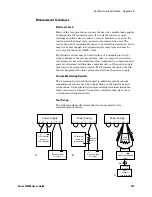
Страница 101: ...ltmeters settling times and slew rates of the power supply may have to be taken into account Wait statements can be used in the test program if the test system is faster than the power supply Current Monitoring Resistor The 4 terminal current shunt is used to eliminate output current measurement error caused by voltage drops in the load leads and connections It has special current monitoring termi...

Страница 102: ...test record for the model being tested under Voltage Programming and Readback Minimum Voltage Vout 4 Program the output voltage to its full scale rating 5 Record the output voltage readings on the DVM as well as the measurement readback The readings should be within the limits specified in the test record for the appropriate model under Voltage Programming and Readback High Voltage Vout CV Load Ef...

Страница 103: ...een the DVM reading in steps 6 and 8 is the source effect which should not exceed the value listed in the test record for the appropriate model under CV Source Effect CV Noise Test category performance Periodic and random deviations in the output combine to produce a residual AC voltage superimposed on the DC output voltage This residual voltage is specified as the rms or peak to peak output volta...

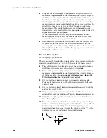
Страница 104: ...ime Test category performance This measures the time for the output voltage to recover to within the specified value following a 10 to 90 change in the load current 6 Turn off the power supply and connect the output as in figure A with the oscilloscope across the S and S terminals 7 Turn on the power supply and program the output current to its maximum programmable value Imax and the output voltag...

Страница 105: ...oltage drop DVM reading across the current shunt by its resistance to convert to amps and record this value Iout Also record the current measurement readback The readings should be within the limits specified in the test record for the appropriate model under Current Programming and Readback High Current Iout CC Load Effect Test category performance This test measures the change in output current ...

Страница 106: ...eaks of the output current ripple several DC measurements should be made and averaged If you are using a Keysight 3458A you can set up the voltmeter to do this automatically From the instrument s front panel program 100 power line cycles per measurement Press NPLC 100 ENTER 4 Turn on the power supply and program the output current to its full scale value and the output voltage to its maximum progr...

Страница 107: ...ing Readback Minimum Current Iout Measurement Readback High Current Iout Measurement Readback 1 6 A Iout 1 2 A 398 8 A Iout 1 6 A _____________ _____________ _____________ _____________ 3 2 A Iout 1 2 A 401 2 A Iout 1 6 A CC Load Effect 85 mA _____________ 85 mA CC Source Effect 42 mA _____________ 42 mA WARNING Return the voltage and current settings to zero when verification is completed Test De...

Страница 108: ... Readback Minimum Current Iout Measurement Readback High Current Iout Measurement Readback 1 3 A Iout 990 mA 329 01 A Iout 1 32 A _____________ _____________ _____________ _____________ 2 6 A Iout 990 mA 330 99 A Iout 1 32 A CC Load Effect 71 mA _____________ 71 mA CC Source Effect 35 mA _____________ 35 mA WARNING Return the voltage and current settings to zero when verification is completed Test...

Страница 109: ...back Minimum Current Iout Measurement Readback High Current Iout Measurement Readback 0 88 A Iout 660 mA 219 34 A Iout 880 mA _____________ _____________ _____________ _____________ 1 76 A Iout 660 mA 220 66 A Iout 880 mA CC Load Effect 49 mA _____________ 49 mA CC Source Effect 24 mA _____________ 24 mA WARNING Return the voltage and current settings to zero when verification is completed Test De...

Страница 110: ...imum Current Iout Measurement Readback High Current Iout Measurement Readback 660 mA Iout 495 mA 164 505 A Iout 660 mA _____________ _____________ _____________ _____________ 1 32 A Iout 495 mA 165 495 A Iout 660 mA CC Load Effect 38 mA _____________ 38 mA CC Source Effect 18 5 mA _____________ 18 5 mA WARNING Return the voltage and current settings to zero when verification is completed Test Desc...

Страница 111: ...back Minimum Current Iout Measurement Readback High Current Iout Measurement Readback 440 mA Iout 330 mA 109 67 A Iout 440 mA _____________ _____________ _____________ _____________ 880 mA Iout 330 mA 110 33 A Iout 440 mA CC Load Effect 27 mA _____________ 27 mA CC Source Effect 13 mA _____________ 13 mA WARNING Return the voltage and current settings to zero when verification is completed Test De...

Страница 112: ...k Minimum Current Iout Measurement Readback High Current Iout Measurement Readback 340 mA Iout 255 mA 84 745 A Iout 340 mA _____________ _____________ _____________ _____________ 680 mA Iout 255 mA 85 255 A Iout 340 mA CC Load Effect 22 mA _____________ 22 mA CC Source Effect 10 5 mA _____________ 10 5 mA WARNING Return the voltage and current settings to zero when verification is completed Test D...

Страница 113: ...back Minimum Current Iout Measurement Readback High Current Iout Measurement Readback 220 mA Iout 165 mA 54 835 A Iout 220 mA _____________ _____________ _____________ _____________ 440 mA Iout 165 mA 55 165 A Iout 220 mA CC Load Effect 16 mA _____________ 16 mA CC Source Effect 7 5 mA _____________ 7 5 mA WARNING Return the voltage and current settings to zero when verification is completed Test ...

Страница 114: ...ack Minimum Current Iout Measurement Readback High Current Iout Measurement Readback 168 mA Iout 126 mA 41 874 A Iout 168 mA _____________ _____________ _____________ _____________ 336 mA Iout 126 mA 42 126 A Iout 168 mA CC Load Effect 13 4 mA _____________ 13 4 mA CC Source Effect 6 2 mA _____________ 6 2 mA WARNING Return the voltage and current settings to zero when verification is completed Te...

Страница 115: ...ack Minimum Current Iout Measurement Readback High Current Iout Measurement Readback 132 mA Iout 99 mA 32 901 A Iout 132 mA _____________ _____________ _____________ _____________ 264 mA Iout 99 mA 33 099 A Iout 132 mA CC Load Effect 11 6 mA _____________ 11 6 mA CC Source Effect 5 3 mA _____________ 5 3 mA WARNING Return the voltage and current settings to zero when verification is completed Test...

Страница 116: ... Readback Minimum Current Iout Measurement Readback High Current Iout Measurement Readback 88 mA Iout 66 mA 21 934 A Iout 88 mA _____________ _____________ _____________ _____________ 176 mA Iout 66 mA 22 066 A Iout 88 mA CC Load Effect 9 4 mA _____________ 9 4 mA CC Source Effect 4 2 mA _____________ 4 2 mA WARNING Return the voltage and current settings to zero when verification is completed Tes...

Страница 117: ... Iout Measurement Readback High Current Iout Measurement Readback 44 mA Iout 33 mA 10 967 A Iout 44 mA _____________ _____________ _____________ _____________ 88 mA Iout 33 mA 11 033 A Iout 44 mA CC Load Effect 7 2 mA _____________ 7 2 mA CC Source Effect 3 1 mA _____________ 3 1 mA WARNING Return the voltage and current settings to zero when verification is completed Test Description N8741A Setti...

Страница 118: ...Measurement Readback High Current Iout Measurement Readback 22 mA Iout 16 5 mA 5 4835 A Iout 22 mA _____________ _____________ _____________ _____________ 44 mA Iout 16 5 mA 5 5165 A Iout 22 mA CC Load Effect 6 1 mA _____________ 6 1 mA CC Source Effect 2 6 mA _____________ 2 6 mA WARNING Return the voltage and current settings to zero when verification is completed Test Description N8742A Setting...

Страница 119: ...eadback Minimum Current Iout Measurement Readback High Current Iout Measurement Readback 1 A Iout 750 mA 249 A Iout 1 0 A _____________ _____________ _____________ _____________ 2 5 A Iout 750 mA 251 A Iout 1 0 A CC Load Effect 250 mA _____________ 250 mA CC Source Effect 125 mA _____________ 125 mA WARNING Return the voltage and current settings to zero when verification is completed Test Descrip...

Страница 120: ...ack Minimum Current Iout Measurement Readback High Current Iout Measurement Readback 0 68 A Iout 510 mA 169 32 A Iout 680 mA _____________ _____________ _____________ _____________ 1 70 A Iout 510 mA 170 68 A Iout 680 mA CC Load Effect 170 mA _____________ 170 mA CC Source Effect 85 mA _____________ 85 mA WARNING Return the voltage and current settings to zero when verification is completed Test D...

Страница 121: ...inimum Current Iout Measurement Readback High Current Iout Measurement Readback 0 50 A Iout 375 mA 124 5 A Iout 500 mA _____________ _____________ _____________ _____________ 1 25 A Iout 375 mA 125 5 A Iout 500 mA CC Load Effect 125 mA _____________ 125 mA CC Source Effect 62 5 mA _____________ 62 5 mA WARNING Return the voltage and current settings to zero when verification is completed Test Desc...

Страница 122: ...ack Minimum Current Iout Measurement Readback High Current Iout Measurement Readback 340 mA Iout 255 mA 84 66 A Iout 340 mA _____________ _____________ _____________ _____________ 850 mA Iout 255 mA 85 34 A Iout 340 mA CC Load Effect 85 mA _____________ 85 mA CC Source Effect 42 5 mA _____________ 42 5 mA WARNING Return the voltage and current settings to zero when verification is completed Test D...

Страница 123: ...adback Minimum Current Iout Measurement Readback High Current Iout Measurement Readback 260 mA Iout 195 mA 64 74 A Iout 260 mA _____________ _____________ _____________ _____________ 650 mA Iout 195 mA 65 26 A Iout 260 mA CC Load Effect 65 mA _____________ 65 mA CC Source Effect 32 5 mA _____________ 32 5 mA WARNING Return the voltage and current settings to zero when verification is completed Tes...

Страница 124: ... Readback Minimum Current Iout Measurement Readback High Current Iout Measurement Readback 200 mA Iout 150 mA 49 8 A Iout 200 mA _____________ _____________ _____________ _____________ 500 mA Iout 150 mA 50 2 A Iout 200 mA CC Load Effect 50 mA _____________ 50 mA CC Source Effect 25 mA _____________ 25 mA WARNING Return the voltage and current settings to zero when verification is completed Test D...

Страница 125: ...g Readback Minimum Current Iout Measurement Readback High Current Iout Measurement Readback 136 mA Iout 102 mA 33 864 A Iout 136 mA _____________ _____________ _____________ _____________ 340 mA Iout 102 mA 34 136 A Iout 136 mA CC Load Effect 34 mA _____________ 34 mA CC Source Effect 17 mA _____________ 17 mA WARNING Return the voltage and current settings to zero when verification is completed T...

Страница 126: ...Iout Measurement Readback High Current Iout Measurement Readback 68 mA Iout 51 mA 16 932 A Iout 68 mA _____________ _____________ _____________ _____________ 170 mA Iout 51 mA 17 068 A Iout 68 mA CC Load Effect 17 mA _____________ 17 mA CC Source Effect 8 5 mA _____________ 8 5 mA WARNING Return the voltage and current settings to zero when verification is completed Test Description N8761A Setting...

Страница 127: ...asurement Readback High Current Iout Measurement Readback 34 mA Iout 25 5 mA 8 466 A Iout 34 mA _____________ _____________ _____________ _____________ 85 mA Iout 25 5 mA 8 534 A Iout 34 mA CC Load Effect 8 5 mA _____________ 8 5 mA CC Source Effect 4 3 mA _____________ 4 3 mA WARNING Return the voltage and current settings to zero when verification is completed Test Description N8762A Settings Vo...

Страница 128: ...completed the instrument saves the calibration constants and begins using them Exit the calibration mode Note that a Reset command RST also sets the calibration state to OFF Calibration Procedure Unless instructed otherwise connect the sense terminal to the output and the sense terminal to the output When calibrating the unit using SCPI commands most calibration steps involve sending an OPC query ...

Страница 129: ...ect the Keysight 3458A across the shunt The shunt should be able to measure at least 120 of the power supply s rated full scale current Step 2 Enable current calibration mode RST OUTP ON CAL STAT ON Step 3 Set the output voltage high enough to compensate for any voltage drops on the load leads and current shunt VSET 0 5 Step 4 Select current calibration CAL CURR Step 5 Select the first current cal...

Страница 130: ......

Страница 131: ...pment 132 Operating Checklist 132 Error Messages 134 Recycling Plastic Components 138 This chapter discusses the procedures involved for returning a failed instrument to Keysight Technologies for service or repair A procedure is included for diagnosing specific symptoms ...

Страница 132: ...l for shipping Secure the container with strong tape or metal bands If the original shipping container is not available place your unit in a container that will ensure at least 4 inches of compressible packaging material around all sides for the instrument Use static free packaging materials to avoid additional damage to your unit Keysight Technologies suggests that you always insure shipments Ope...

Страница 133: ...ont panel CV LED is on Is the unit in constant voltage mode Check the current limit and voltage setting Large ripple present in output Is the power supply in remote sense Is the voltage drop on the load wire high Check load and sense wires connection for noise and impedance effects Minimize the drop on the load wires No output Display indicates OUP Over voltage circuit has tripped Turn off the POW...

Страница 134: ...eric format yyyy year mm month dd date 203 Compatibility function not implemented The requested compatibility function is not available 204 NVRAM checksum error A checksum error has occurred in the instrument s nonvolatile random access memory 205 NVRAM full The nonvolatile random access memory of the instrument is full 206 File not found The internal calibration file or the internal channel attri...

Страница 135: ... that was not a valid header separator was found in the command string 112 Program mnemonic too long The header contains more than 12 characters 113 Undefined header A command was received that was not valid for this instrument 114 Header suffix out of range The value of the numeric suffix is not valid 120 Numeric data error Generic numeric data error 121 Invalid character in number An invalid cha...

Страница 136: ...rary block format but is not allowed for this command 170 Expression error Generic expression error 171 Invalid expression data The expression data element was invalid 178 Expression data not allowed Expression data element was sent but is not allowed for this command Execution Errors these errors set Standard Event Status register bit 4 200 Execution error Generic syntax error 220 Parameter error...

Страница 137: ...ion 260 Expression error An expression program data element related error occurred 261 Math error in expression An expression program data element could not be executed due to a math error Query Errors these errors set Standard Event Status register bit 2 400 Query Error Generic error query 410 Query INTERRUPTED A condition causing an interrupted query error occurred 420 Query UNTERMINATED A condi...

Страница 138: ... 2 CYCOLOY C6200 Airflow deflector clear qty 1 LEXAN FR60 Pushbuttons qty 6 CYCOLOY C6200 FET dust shield clear qty 2 LEXAN FR60 Nameplate qty 1 8B35V FET diode insulator pink assorted sizes qty varies TC 30 CG Controls label qty 1 8010VC Bus bar spacers red black qty 2 VALOX 310 SEO Foot qty 4 AR 790 Fan push rivet black qty 12 NYLON 6 Analog connector cover qty 2 LEXAN 243R PCB standoff white qt...

Страница 139: ...atically compatible with the Keysight 603xA power supplies This means that you can remotely program the Keysight N8700 power supplies using the same commands that are used to program the 603xA power supplies CAUTION Do not mix Compatibility with SCPI commands in the same program This will result in unpredictable instrument behavior ...

Страница 140: ...ommand and finish reading back the information from the original query Sending a second query without reading the response to the first will generate an error Model number queries will only return the N8700 model numbers Status functions Serial Poll will be controlled by the SCPI status model and will not act like a 603xA power supply SRQ will be controlled by the SCPI status model Parallel poll w...

Страница 141: ...s the OCP on or off This is only allowed for constant current mode FOLD 2 Constant voltage mode FOLD1 generates error 203 CURR PROT STAT FOLD Queries the OCP setting The response is FOLD 2 CURR PROT STAT HOLD When turned on HOLD 1 causes the VSET ISET FOLD and UNMASK values to be held until a trigger occurs This only applies to the compatibility functions not the SCPI functions VOLT TRIG CURR TRIG...

Страница 142: ...s in the mask register to the setting The setting is an integer that represents the sum of the binary weights of the bits The mask register operates in conjunction with the status and fault registers STAT OPER NTR STAT OPER PTR STAT QUES NTR STAT QUES PTR UNMASK Note 1 Queries the present setting of the mask register The response is UNMASK n STAT OPER NTR STAT OPER PTR STAT QUES NTR STAT QUES PTR ...

Страница 143: ...m different subsystems 64 root specifier 64 command completion 67 synchronization 67 common commands 69 CLS 80 ESE 81 ESR 81 IDN 84 OPC 81 OPT 84 RCL 84 RST 84 SAV 84 SRE 82 STB 82 TST 84 WAI 82 TRG 85 common mode current 33 compatibility command summary 141 differences 140 connections 6V to 60V models 27 80V to 600V models 27 analog 16 J137 J229 multiple load 31 parallel 33 sense 15 series 35 ser...

Страница 144: ...2 inductive loads 32 initiate commands INIT 85 INIT CONT 85 inspection 18 IO54 IP Address 60 items supplied 18 J J1 connector 14 J2 connector 14 K keywords 64 L LAN 13 LAN interface 55 sockets 59 Telnet 59 62 LAN private 57 LAN site 56 last setting memory 46 LFP 13 LIMIT 13 load wiring 25 local voltage sensing 29 lock front panel 45 M magnetic fields 19 master unit 34 MAV 82 measure commands 73 ME...

Страница 145: ...e start 46 safety 5 19 SCPI command completion 67 command path 63 commands 70 device clear 67 message unit 64 multiple commands 63 syntax 63 shut off terminals 46 slave unit 34 sockets 59 source commands 75 SOUR CURR IMM 75 SOUR CURR PROT STAT 75 SOUR CURR TRIG 75 SOUR VOLT IMM 75 SOUR VOLT LIM LOW 76 SOUR VOLT PROT LEV 76 SOUR VOLT TRIG 75 specifications characteristics 95 performance 94 status c...

Страница 146: ...nder voltage limit 44 USB ID string 55 USB interface 55 UUL 13 UVL 13 V verification 99 verification equipment 100 VOLTAGE 12 voltage monitoring external 52 voltage programming accuracy 102 voltage readback accuracy 102 voltage sensing 29 W warning 5 Web server 58 web URL s 6 wire sizes 25 ...

Страница 147: ...This information is subject to change without notice Keysight Technologies 2009 2014 Edition 4 November 2014 N8700 90001 N8700 90001 www keysight com ...

Отзывы: