


3
4
Keysight M9018A PXIe 18-Slot Chassis Startup Guide
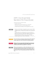
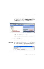
STEP 3: Turn On and Verify Operation of the Chassis System
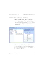
Using the soft front panel to monitor the chassis
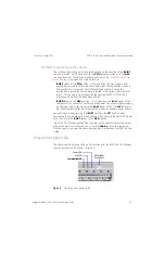
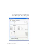
As you can see, there are seven Alarm Occurred indicators on the right side of
the
M onitor
screen. These alarms are enabled by default and operate as
described in Table 6. If the chassis is operating normally and is using the default
alarm thresholds, none of the alarms should be set. For information on
configuring these alarms to other than their default thresholds, please see the
M9018A User Guide.
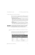
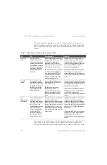
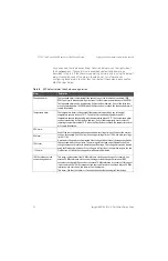
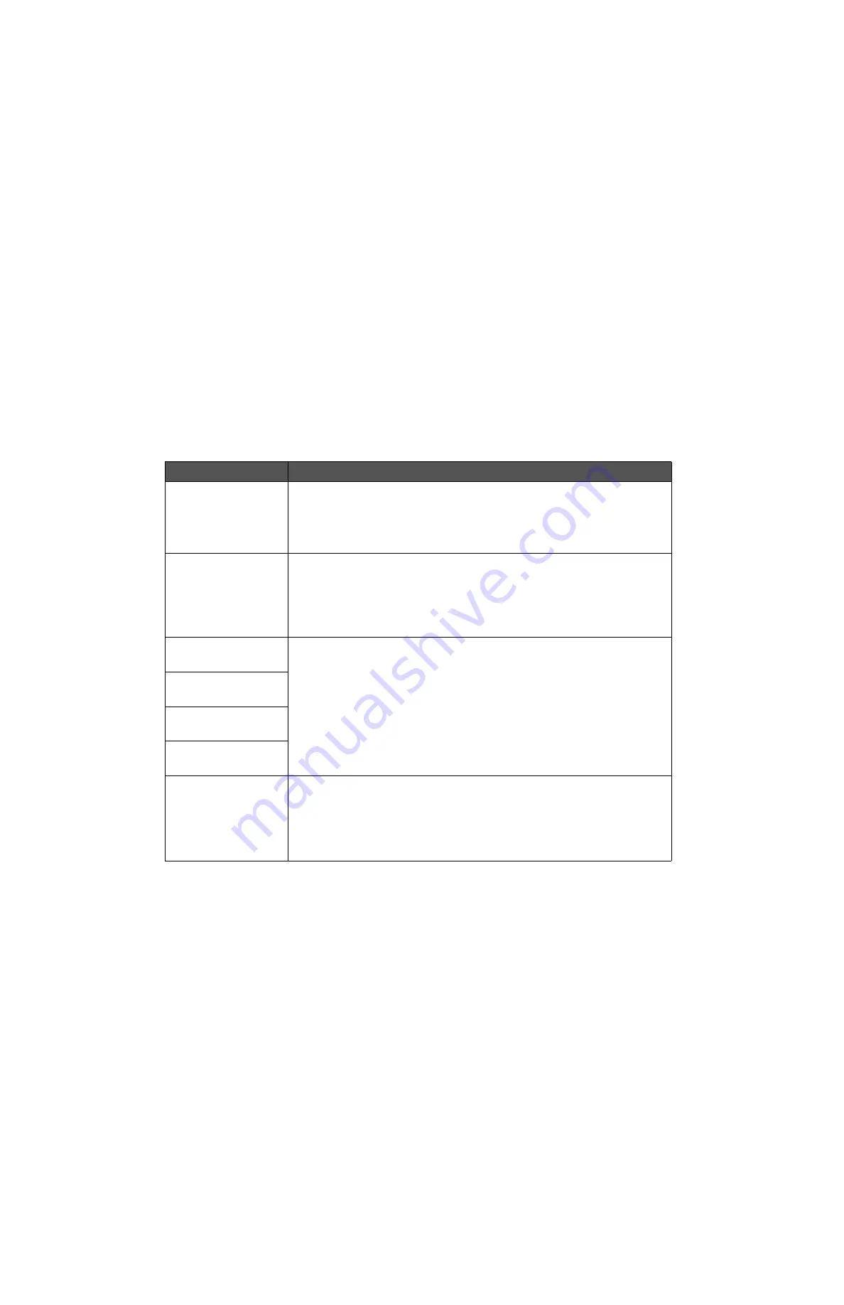
Table 6
SFP default alarm thresholds and operation
Alarm
Description
Fan speed alarm
The fan speed alarm is illuminated if the speed of any of the three fans drops below 1000
RPM. The alarm is latched and will persist even if all fans resume operation above 1000 RPM.
The fan speed alarm can be cleared using its Clear button; however, if any of the three fans
are still operating below 1000 RPM when the Clear button is clicked, the fan speed alarm will
remain illuminated.
Temperature alarm
The temperature alarm is illuminated if the temperature reported by any of the eight
temperature sensors is above 70 °C. The alarm is latched and will persist even if all
temperature sensors subsequently report temperatures below 70 °C. The temperature alarm
can be cleared using its Clear button; however, if any of the temperature sensors are still
reporting a temperature above 70 °C when the Clear button is clicked, the temperature alarm
will remain illuminated.
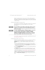
3.3V alarm
Each of the four voltage alarms has upper and lower voltage limits of 5% about the nominal
voltage. For example, the 12V alarm has an upper voltage limit of 12.6V and a lower voltage
limit of 11.4V.
A particular voltage alarm is illuminated if that voltage falls outside of the range specified by
the upper and lower voltage limits. The alarm signal is latched and will persist even if the
voltage subsequently returns to within the specified range. The voltage alarm can be cleared
using the Clear button; however, if the voltage is still outside of the specified range when the
Clear button is clicked, the voltage alarm will remain illuminated.
5V alarm
12V alarm
-12V alarm
10 MHz reference clock
source changed alarm
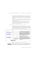
This alarm is illuminated if the 10 MHz reference clock source changes. For example, if an
external 10 MHz reference clock source is being provided through the rear panel BNC
connector, that signal will be used as the chassis 10 MHz reference clock source. If this signal
is disconnected, the 10 MHz reference clock source will revert to the chassis internal 10 MHz
reference clock source, and this alarm will be illuminated.
This alarm, like the other alarms, is latched and can be cleared using its Clear button.


