
8
Keysight M9018A PXIe 18-Slot Chassis Startup Guide
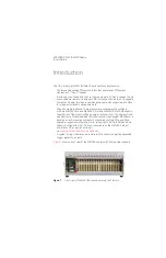
Introduction
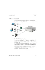
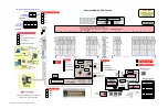
M9018A interactive block diagram
Because the interactive block diagram uses JavaScript, you may be prompted to
enable JavaScript—select
Yes
if asked. If you’re not prompted to enable
JavaScript and need to do so in order to make the diagram interactive, look for
the enable JavaScript check box as follows on Adobe Acrobat and Adobe
Reader:
Edit > Preferences > JavaScript
If you print the block diagram, use a tabloid-capable printer (11”x17”, which is
the page size of the diagram). The diagram can also be printed on letter size
paper by selecting “Fit to Printable Area” or equivalent.
Features selected using the check boxes will print the same as viewed on your
monitor. However, mouse-over popups are not printable.
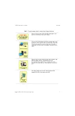
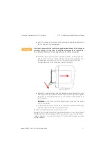
Click Front View to view a labeled drawing of the front of the chassis, and
click Rear View to view a labeled drawing of the rear of the chassis.
Of particular importance in the front view is the M9021A power slide
switch, which must be positioned to the right to power the M9021A PCIe
Cable Interface module, and must be positioned to the left for all other
slot 1 modules.
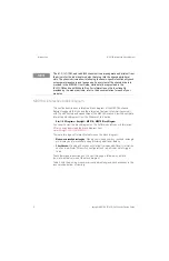
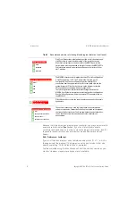
The M9018A chassis currently implements three PCIe link configurations,
2-Link Configuration: 1x8, 2-Link Configuration: 2x8, and 4-Link
Configuration: 4x4. These configurations provide different PCIe
connections from the system controller slot to the hybrid slots and the
system timing slot. Click the check boxes on the diagram to view the
PCIe connections associated with each configuration.
The 1x8 configuration is the factory default configuration; see the
M9018A User Guide for information on selecting the other configurations.
Use the 1x8 configuration with laptop computer PCIe adapters such as
the M9045A/B.
Click this check box to view the type of boards supported by the chassis
hybrid slots.
These check boxes can be used to display the two key user interface
software components, Connection Expert and the chassis soft front panel,
that run on the host controller. The Development environments check box
can be checked to view the supported application development
environments.
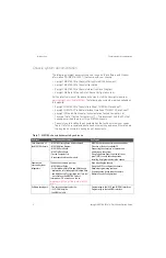
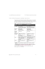
Table 2
Recommended order of viewing block diagram features (continued)
Show Chassis Views
Clear
F
t Vi
Front View
Rear View
Show PCIe Link Configurations
Clear
1x8
2x8
4x4
Show Boards Supported
by the Hybrid Slots
6KRZ+RVW&RQWUROOHU6RIWZDUH
&OHDU
.H\VLJKW&RQQHFWLRQ([SHUW
6RIW)URQW3DQHO
'HYHORSPHQWHQYLURQPHQWV


