background image

Keysight B1500A Configuration and Connection Guide, Edition 6

3-27

Connection Guide for Wafer Prober

Interlock circuit

4. Use wire to connect the two switches in series between pin number 1 and 2 (or 3) of the 

interlock connector. See Figure 3-28.

5. Use wire to connect the LED between pin number 4 and 5 (or 6) of the interlock 

connector. See Figure 3-28.

6. Attach the interlock connector to the mounting hole.

If Keysight B1500A Interlock connector is connected to the interlock circuit, Keysight 
B1500A SMU 

cannot

 force more than ± 42 V when the door is open. When the door is 

closed, it can force more than ± 42 V.

When more than ± 42 V is forced from an SMU, the LED lights to indicate 

high voltage 

output

.

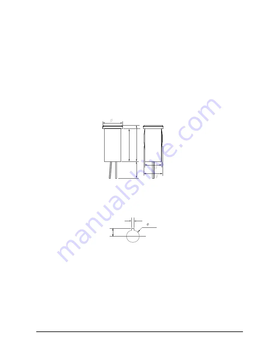
Figure 3-29

Dimensions of the LED (Keysight part number 1450-0641) 

Figure 3-30

Dimensions of Mounting Hole for the Interlock Connector

6

10

11

5

5.6

5

Units : mm

Anode (+)

Cathode (

-

)

1.8

8.2

5.1

Содержание B1500A Series

Страница 1: ...Keysight B1500A Semiconductor Device Analyzer Configuration and Connection Guide...

Страница 2: ...ocument that conflict with these terms the war ranty terms in the separate agreement shall control Technology Licenses The hardware and or software described in this document are furnished under a lic...

Страница 3: ...ion mode 1 27 Application library 1 28 Oscilloscope view 1 28 Workspace and data management 1 29 External instrument control 1 29 Furnished Software 1 29 Desktop EasyEXPERT Software 1 30 System requir...

Страница 4: ...rcuit 3 26 Installing the interlock circuit 3 26 To connect interlock circuit 3 28 4 Connection and Ordering Examples Two terminal device 4 2 General IV characterization 4 2 General IV CV characteriza...

Страница 5: ...1 B1500A Product Configuration...

Страница 6: ...ter by using Keysight FLEX command set that is the common language for Keysight semiconductor DC measurement instruments So you can reuse the measurement program created for Keysight 4155 4156 E5260 E...

Страница 7: ...e measurement resource can be HV SPGU or SMU Needs the 16445A adapter to use the selector One selector provides two switching channel 16442B test fixture B1500A A5F Test fixture for semiconductor para...

Страница 8: ...h for many new device structures Table 1 1 Mainframe Specification Table 1 2 SMU Module Variation Available Slots 10 Ground Unit GNDU sink capability 4 2 A Instrument control GPIB External trigger inp...

Страница 9: ...Keysight B1500A Configuration and Connection Guide Edition 6 1 5 B1500A Product Configuration Product line up of the B1500A series Figure 1 1 B1500A Rear View...

Страница 10: ...ry B1500A A00 Empty package for custom solution No module is included in B1500A mainframe Specify Add on package option B1500A A01 Standard pack 1 Standard package Mid PWR unit 4ea cables Standard pac...

Страница 11: ...current source monitor unit 2ea w connection box 50 s pulse MCSMU two modules add on package adds two MCSMU four triaxial cables and the N1255A connection box Cable length 1 5 m or 3 0 m is specified...

Страница 12: ...for furnished accessories Specify the cable length mandatory B1500A 015 1 5 m cable 1 5 m cable length for mainframe bundled cables and for package options B1500A 030 3 0 m cable 3 0 m cable length f...

Страница 13: ...ive DVD ROM drive option for higher security Replace from DVD RW to DVD ROM Select rack mount kit optional B1500A 1CM Rack mount kit Rack mount kit for the B1500A 7U height EIA Select WGFMU learning k...

Страница 14: ...ons are described in this chapter Table 1 4 Furnished accessories on the B1500A semiconductor device analyzer mainframe Description Qty Note USB keyboard 1 USB Keyboard for the B1500A USB mouse 1 USB...

Страница 15: ...xial cable must be used for the Sense Triaxial cable 1 Cable length 1 5 m or 3 0 m is specified by the option B1500A 015 or B1500A 030 Power cable 1 Power cable for the B1500A Software CD 1 Desktop Ea...

Страница 16: ...cription Qty Note HRSMU 4 Installed High resolution source monitor unit HRSMU Triaxial cable 8 Cable length 1 5 m or 3 0 m is specified by the option B1500A 015 or B1500A 030 Description Qty Note MPSM...

Страница 17: ...0A and 16445A 16445A 001 Control cable 40 cm 1 Control cable 40 cm between 16445A and 16440A 16440A 003 Triaxial cable 1 5 m 2 Cable length 1 5 m for 16440A pulse selector Triaxial cable 8 Cable lengt...

Страница 18: ...ngth 1 5 m or 3 0 m is specified by the option B1500A 015 or B1500A 030 Description Qty Note MCSMU 1 Installed Medium current source monitor unit MCSMU Triaxial cable 2 Cable length 1 5 m or 3 0 m is...

Страница 19: ...tor unit Description Qty Note MFCMU 1 Installed Multi frequency capacitance measurement unit MFCMU CMU cable 1 CMU Cable for B1500 N1300A Cable length 1 5 m or 3 0 m is specified by the option B1500A...

Страница 20: ...PSMU Description Qty Note ASU 1 Atto sense switch unit E5288A ASU 1 ea Triaxial and D sub cable for ASU 1 Triaxial D sub Cable for ASU 16493M Cable length 1 5 m or 3 0 m is specified by the option B15...

Страница 21: ...le between WGFMU and RSU Cable length 1 5 m or 3 0 m is specified by the option B1500A 015 or B1500A 030 Description Qty Note WGFMU 1 Installed Waveform generator fast measurement unit WGFMU RSU 2 Rem...

Страница 22: ...able kit for WGFMU Description Qty Note SSMC cable 50 mm 2 SSMC short open cable for current return path 50 mm 16493R 101 SSMC cable 70 mm 2 SSMC short open cable for current return path 70 mm 16493R...

Страница 23: ...ckage socket module Universal socket module 1 Universal socket module 0 075 inch pitch Universal socket module 1 Universal socket module 0 05 inch pitch Connection pin set 10 Connection pin set for un...

Страница 24: ...the B1500A mainframe This module consumes 2 slots B1500AU 11B Addition of B1511B Medium power source monitor unit module 100 mA 100 V 10 fA 0 5 V resolution Medium power source monitor unit module for...

Страница 25: ...N1255A Connection box and Triaxial cables It requires two Triaxial cables B1500AU 020 Addition of B1520A Multi frequency capacitance measurement unit module 1 kHz to 5 MHz frequency range 25 V dc bia...

Страница 26: ...n of N1300A 002 CMU cable for B1500 3m B1500AU S01 Addition of two 16493P 001 SPGU cables 1 5m SPGU output connection cable SMA to Coaxial SPGU cable is optional and length is specified by option S01...

Страница 27: ...configuration and serial number Contact Keysight Technologies to upgrade the B1500A Drive option B1500AU DR1 Replace DVD R drive with read only drive available for S N JP49090101 or later It is avail...

Страница 28: ...RSU and WGFMU for installing WGFMU For returning ASU or RSU do not forget to notify the combination of the unit connection cable and module channel WARNING To prevent electrical shock turn off Keysigh...

Страница 29: ...PSMU and one CMU the B1500A will be shipped with the HPSMUs of the slots 1 to 4 the MPSMUs of the slots 5 to 6 the CMU of the slot 7 and the blank panels of the slots 8 to 10 Table 1 24 Module Install...

Страница 30: ...lowing formula due to the limitation of the power consumption Total number of Number of Module Factor for each module must be under 59 Including 59 For example configuration with 5 WGFMU and 5 MPSMU t...

Страница 31: ...rsion of the EasyEXPERT update package can be obtained from Keysight Technologies web site Operation mode The EasyEXPERT has the following measurement operation environments Application test mode The...

Страница 32: ...sing MCSMU modules The oscilloscope view displays MCSMU current or voltage measurement data versus time The pulsed measurement waveforms appear in a separate window for easy verification of the measur...

Страница 33: ...tion with a semiautomatic wafer prober The following shows supported equipment list Switching matrix operation panel GUI Keysight B2200A B2201A and E5250A with E5252A cards External instruments suppor...

Страница 34: ...e tracer 4155B 4155C Semiconductor parameter analyzer 4156B 4156C Precision semiconductor parameter analyzer Supported 4155 4156 functionality I V sweep I V t sampling except thinned out mode VSU VMU...

Страница 35: ...nistrator privilege which is required by the revision A 03 11 and previous revisions However if the software is updated from a previous revision to the revision A 03 20 or later it still requires the...

Страница 36: ...1500A Product Configuration EasyEXPERT and Desktop EasyEXPERT software used to send and receive commands queries and query responses All commands must be terminated with a newline for the message to b...

Страница 37: ...S EasyEXPERT Extension Figure 1 2 License management tool in the B1500A NOTE The EasyEXPERT software revision 5 5 or later requires license of Keysight EasyEXPERT Extension B1500A SWS or B1500A SWS To...

Страница 38: ...Technologies to upgrade the B1500A NOTE How to get the license file lic file for SWS Extension The license file lic file for SWS Extension can be gotten on the following web site with order number ce...

Страница 39: ...cense to use media and manual 1 Pulsed IV package software CD ROM Drain cable compensation data CD ROM Desktop EasyEXPERT software CD ROM B1542A User s Guide English Drain cable set 1 Triaxial cable 1...

Страница 40: ...ecommended However it may be used if you change the connections manually Because the pulsed IV measurement uses one SMU and the DC IV measurement uses only 2 ea of SMU Description Remarks 54853A 54854...

Страница 41: ...sktop EasyEXPERT application test environment without creating the test programs The B1542A also provides the test definition used for the system setup Pulsed IV Id Vd characteristics measurement Puls...

Страница 42: ...1 38 Keysight B1500A Configuration and Connection Guide Edition 6 B1500A Product Configuration B1542A Pulsed IV package for B1500A...

Страница 43: ...2 B1500A Accessories...

Страница 44: ...m Kelvin Triaxial cables should be employed when performing very sophisticated measurements GNDU cables have a very similar face to Triaxial cables However the configuration of signal path is differen...

Страница 45: ...16494B 002 Kelvin triaxial cable to E5250A switching matrix input port 3 m 16494B 003 Kelvin triaxial cable to E5250A switching matrix input port 80 cm GNDU cable 16493L 001 GNDU cable 1 5 m 16493L 0...

Страница 46: ...cables so that cable can be compensated B1520A MFCMU has very thin module design so 16048D E cannot connect with B1500A SCUU SMU CMU unify unit is used to switch the module CMU or SMU to be connected...

Страница 47: ...vender The prober vender will have the solutions Dimensions of the SCUU are 148 mm W 75 mm H 70 mm D Dimensions of the GSWU are 33 2 mm W 41 5 mm H 32 8 mm D NOTE About SCUU output cables To perform c...

Страница 48: ...asurement resource connected to the DUT The measurement resource can be SPGU or SMU Needs the 16445A adapter to use the selector One selector provides two switching channels Digital I O cables General...

Страница 49: ...nal properly Connecting to the other terminal may result in damage to the SPGU 16445A SMU PGU selector connection adapter furnished with digital I O control cable 16445A 001 Control cable for B1500A t...

Страница 50: ...MU module to RSU The 16495H 001 or 16495J 001 connector plate is required and mounted on a shielding box to make connection to the RSU in the shielding box Then the 80 cm or 40 cm triaxial cable is ad...

Страница 51: ...ls will pass the self test and skip the self calibration But controlling the channel will cause a run time error NOTE Cables used for the same measurement Connect all measurement cables to the appropr...

Страница 52: ...The following items are shipped as standard with the 16442B test fixture Blank PTFE board 28 pin dual in package DIP socket module 0 075 inch universal socket module 0 5 inch universal socket module M...

Страница 53: ...inch pitch with 10 pins 16442B 810 Extra pin set for universal socket module 10 pins 16442B 811 Extra wire set mini banana to pin plug 6 ea 16442B 812 Extra wire set pin plug to pin plug 6 ea 16442B 8...

Страница 54: ...escription Additional Information Accessories for B1500A 16444A 001 Extra USB keyboard 16444A 002 Extra USB mouth 16444A 003 Extra Stylus pen Interlock cable 16493J 001 Interlock cable 1 5 m 16493J 00...

Страница 55: ...O port with BNC trigger port of other instruments Box which has 8 BNC connectors for connecting with BNC trigger port of other instruments and 25 pin D sub connector for connecting this box to B1500A...

Страница 56: ...et Stand for ASU E5288A Accessories for 16442B test fixture N1254A 200 Transistor socket module in 16442B 821 4 pin TO package N1254A 201 28pin DIP socket module in 16442B 823 N1254A 202 18pin DIP soc...

Страница 57: ...ni banana mini banana black 1 ea Mini banana mini banana included in 16442B 814 N1254A 311 Mini banana mini banana red 1 ea Mini banana mini banana included in 16442B 814 N1254A 312 Mini banana mini b...

Страница 58: ...black 1 ea and red 1 ea N1254A 512 SHV cable 250 mm N1254A 513 SHV to banana adapter 1ea N1254A 514 BNC m to BNC m adapter 1 ea N1254A 515 BNC f BNC m BNC f adapter 1 ea N1254A 516 BNC f BNC f BNC f...

Страница 59: ...r Keysight standard cabinet Keysight B1500A can be mounted in a 19 inch EIA rack cabinet It is designed to fit in seven rack units 7U of space Table 2 8 Rack mount parts for B1500A Model Height EIA Ha...

Страница 60: ...plate with 12 triaxial interlock and ground unit connectors Common terminals are connected to plate ATTENTION Must specify either 16495F 001 or 16495F 002 16495F 001 Bulkhead feedthru connectors Conn...

Страница 61: ...n type is Connector Connector 16495G 002 Connectors to contacts for soldering Connection type is Connector Solder Item Description OP Instruction 16495H Connector plate with 6 triax 6 BNC intlk GNDU H...

Страница 62: ...ck the light from the cable hole This plate will be used with the E5288A ASU or the N1301A 200 GSWU that will be installed in the shielding box ATTENTION Must specify 16495K 001 16495K 001 Connector p...

Страница 63: ...3 Connection Guide for Wafer Prober...

Страница 64: ...tion with prober 3 1 SMU GNDU connection with prober This section describes how to connect a wafer prober to the Keysight B1500A semiconductor device analyzer Table 3 1 Semi automated prober with B150...

Страница 65: ...a standard triaxial cable The GNDU cable can handle the maximum GNDU current of 4 2 A but standard triaxial cables 16494A are only rated to 1 A Figure 3 1 GNDU terminal Non Kelvin connection Connect...

Страница 66: ...n in Figure 3 3 For parts information see Table 3 3 Maximum current is restricted when the Kelvin triaxial cable is used Figure 3 3 Example of a GNDU Kelvin connection Table 3 3 Item number informatio...

Страница 67: ...nnector on the probe cable as shown in Figure 3 5 For parts information see Table 3 4 NOTE Making non kelvin connection The Force terminals can be used to force and measure DC voltage or current If yo...

Страница 68: ...he FORCE and SENSE lines to probes separately Connect the triaxial connector on the probe cable as shown in Figure 3 6 For parts information see Table 3 5 NOTE To prevent oscillations do not use cable...

Страница 69: ...ations do not use longer than 1 5m if user uses two 16494A triaxial cables with Kelvin connections NOTE When connecting the cable and tee connector as shown in Figure 3 7 space restrictions make an ad...

Страница 70: ...he 16494A triaxial cable Use the following cables to connect the N1255A to the MCSMU 16494A Triaxial cable 2 ea per one MCSMU Use the following cables and adapter to connect the N1255A to the GNDU N12...

Страница 71: ...ing shown in Figure 3 14 Cable and Probing needle can be used To simplify the connections omit the wiring of the Common For the non Kelvin connection use the High Force and the Low Force only Omit the...

Страница 72: ...se line Set the SW4 to 0 if the SW2 is set to Kelvin Set the SW2 to Non Kelvin if the SW4 is set to 100 NOTE Selection switch SW1 SW2 SW3 The switch is used to make or break the connection between For...

Страница 73: ...Panel GNDU SMU MCSMU 1 Sense Force 40 V Max Input High Force Sense Low Force Sense Circuit Common MCSMU 2 Sense Force 40 V Max High Force Sense Low Force Sense Circuit Common Sense Force 200 V Max Fo...

Страница 74: ...r conductor to the probing needle However the outer conductor should be extended as close as possible to the probing needle 3 Connect the outer conductor to the outer conductor of the probing needle i...

Страница 75: ...ing WARNING Do not touch the guard terminal with bare hands because you may be shocked by high voltage The potential of the guard terminal is equal to the output voltage CAUTION Never connect the Guar...

Страница 76: ...does not touch the outer conductor connected to the guard terminal 2 Connect the center conductor to tail of the probing needle Never connect the outer conductor to the probing needle However the out...

Страница 77: ...he Sense line wiring has a residual resistance of 10 or less Therefore the specified voltage appears at the sense point point where Sense line contacts Force line NOTE Kelvin connection and non Kelvin...

Страница 78: ...the SCUU function exactly the same as the Kelvin outputs of an SMU both FORCE and SENSE lines are available NOTE In the Figure 3 17 SENSE lines are not used When making CV measurements using the MFCM...

Страница 79: ...MU via the D sub cable When making CV measurements the four terminal pair 4TP connections are correctly terminated inside of the ASUs The ASUs also allow for a current return path between the outer co...

Страница 80: ...measurement accurately the cable length between DUT and the ASU output must be as short possible NOTE For the installation of the ASU and the connection to the DUT interface probe card manipulators a...

Страница 81: ...ecting RSU Prepare the required accessories and connect cables between RSU and WGFMU or SMU See Figure 3 19 for a connection example This example connects two RSUs Figure 3 19 RSU Connection Example R...

Страница 82: ...o make connection to the RSU in the shielding box Then the 80 cm or 40 cm cable 16494A 003 or 004 is additionally required 16495K 001 plate with cable holder optional Instead of using both 16493R 801...

Страница 83: ...y connected to the ground via the shielding of the measurement path RF probes and measurement cables See Figure 3 23 Figure 3 22 RF probes Prepare two RF probes to perform the RF measurement The RF pr...

Страница 84: ...ectors The recommended tools are listed in the Table 3 9 CAUTION Using cable tie Use a cable tie to secure the cables Then do not tug the cable tie You must treat the RF cables carefully to avoid the...

Страница 85: ...igure 3 25 RSU connection on the Prober Table 3 10 Item number information for WGFMU with RF probing connection Description Qty Option Number Retrofit Kit WGFMU Including two RSU 1 B1500A A30 B1500AU...

Страница 86: ...e connection cables to connect the DC probes together 50 mm length SSMC short open cable Furnished with B1500A A3P Or 16493R 101 70 mm length SSMC short open cable Furnished with B1500A A3P Or 16493R...

Страница 87: ...must be the Drain side This electrically connects the Source probe needle Source probe shield and Drain probe shield together Connect the last SSMC short open cable between the Well DC probe and the...

Страница 88: ...6 1 Installing the interlock circuit Prepare the required parts listed in Table 3 12 And install the interlock circuit as shown below 1 Make mounting hole for the interlock connector See Figure 3 30 f...

Страница 89: ...igure 3 28 6 Attach the interlock connector to the mounting hole If Keysight B1500A Interlock connector is connected to the interlock circuit Keysight B1500A SMU cannot force more than 42 V when the d...

Страница 90: ...hock from high voltage more than 42 V If the interlock circuit is open the B1500A cannot apply high voltage more than 42 V Before performing measurement connect the 16493J interlock cable between the...

Страница 91: ...4 Connection and Ordering Examples...

Страница 92: ...nal devices 4 1 1 General IV characterization Figure 4 1 General IV configuration Table 4 1 Target device and application Table 4 2 Key specification Device Application Note Diode IF VF IR VR Breakdow...

Страница 93: ...tion Description Qty B1500A Semiconductor Device Analyzer Mainframe 1 B1500A 015 030 1 5 m or 3 m length of bundled cables 1 B1500A A00 Empty package for custom solution contains no measurement module...

Страница 94: ...Breakdown C V C f C t Resister R I R V 2 wire or 4 wire Item Range Note Maximum I V range 100 mA 100 V Minimum I V resolution 10 fA 0 5 V CV frequency range 1 kHz to 5 MHz Maximum DC bias to CV 100 V...

Страница 95: ...for custom solution contains no measurement module 1 B1500A A11 MPSMU add on package adds one MPSMU and two triaxial cables 2 B1500A A20 Capacitance measurement add on package adds the MFCMU and one...

Страница 96: ...on Table 4 7 Target device and application Table 4 8 Key specification Device Application Note Diode IF VF IR VR Breakdown Resister R I R V 2 wire or 4 wire Item Range Note Maximum I V range 100 mA 10...

Страница 97: ...th the 16442B test fixture Model option Description Qty B1500A Semiconductor Device Analyzer Mainframe 1 B1500A 015 030 1 5 m or 3 m length of bundled cables 1 B1500A A00 Empty package for custom solu...

Страница 98: ...conductor Device Analyzer for 4 terminal devices 4 2 1 General IV characterization Migration from 4155 Figure 4 4 General IV configuration Table 4 10 Target device and application Device Application N...

Страница 99: ...ple Item Range Note Maximum I V range 100 mA 100 V Minimum I V resolution 10 fA 0 5 V Model option Description Qty B1500A Semiconductor Device Analyzer Mainframe 1 B1500A 015 030 1 5 m or 3 m length o...

Страница 100: ...ice and application Device Application Note FET Id Vd Vth BVdss Id leak Ig leak Cgb Connector plate Fixture Prober DUT Interlock GSWU N1302A 200 GSWU cable N1302A 201 202 G D Subs S MPSMU SCUU cable N...

Страница 101: ...iption Qty B1500A Semiconductor Device Analyzer Mainframe 1 B1500A 015 030 1 5 m or 3 m length of bundled cables 1 B1500A A01 Standard package contains four MPSMU and eight triaxial cables 1 B1500A A2...

Страница 102: ...tion Table 4 16 Target device and application Table 4 17 Key specification Device Application Note FET Id Vd Vth BVdss Id leak Ig leak Item Range Note Maximum I V range 100 mA 100 V Minimum I V resolu...

Страница 103: ...low current level is around 1 nA with the 16442B test fixture Model option Description Qty B1500A Semiconductor Device Analyzer Mainframe 1 B1500A 015 030 1 5 m or 3 m length of bundled cables 1 B150...

Страница 104: ...t device and application Table 4 20 Key specification Device Application Note FET Id Vd Vth BVdss Id leak Ig leak Item Range Note Maximum I V range 100 mA 100 V Minimum I V resolution 0 1 fA 0 5 V HRS...

Страница 105: ...nnect ASU MPSMU B1511B option A11 is also available Model option Description Qty B1500A Semiconductor Device Analyzer Mainframe 1 B1500A 015 030 1 5 m or 3 m length of bundled cables 1 B1500A A02 High...

Страница 106: ...4 22 Target device and application Table 4 23 Key specification Device Application Note FET Id Vd Vth BVdss Id leak Ig leak Item Range Note Maximum I V range 1 A 200 V Minimum I V resolution 10 fA 0 5...

Страница 107: ...24 Configuration Example Model option Description Qty B1500A Semiconductor Device Analyzer Mainframe 1 B1500A 015 030 1 5 m or 3 m length of bundled cables 1 B1500A A03 High power package contains two...

Страница 108: ...xial cable Sense Force B1500A MPSMU Sense Force Interlock cable MCSMU Sense H L Force H L GNDU Froce Sense Sense Force Force N1255A Connection Box Sense Force Force Force Force N1254A 100 GNDU Adapter...

Страница 109: ...rminal by MCSMU Minimum I V resolution 10 fA 0 5 V Gate Substrate terminal by MPSMU Minimum pulse width 50 s Drain terminal by MCSMU Id fast sampling 2 s Drain terminal by MCSMU Model option Descripti...

Страница 110: ...ial cable Sense Force B1500A Interlock cable MCSMU Sense H L Force H L MCSMU Sense H L Force H L GNDU Froce Sense Sense Force Force N1255A Connection Box Sense Force Force Force Force N1254A 100 GNDU...

Страница 111: ...rminal by MCSMU Minimum I V resolution 10 fA 0 5 V Substrate terminal by MPSMU Minimum pulse width 50 s Drain Gate terminal by MCSMU Id fast sampling 2 s Drain Gate terminal by MCSMU Model option Desc...

Страница 112: ...aracterization MPSMU Triaxial cable Sense Force B1500A MPSMU Sense Force Interlock cable HRSMU Sense Force HRSMU Sense Force HVSPGU Channel 2 Channel 1 PGU 1 SMU 1 Output 1 16440A Selector PGU 2 SMU 2...

Страница 113: ...rase and Vth test Write and Vth test Retention test Word disturb test Requires 2 pulse channels FET Charge pumping Item Range Note Maximum I V range 100 mA 100 V Minimum I V resolution 10 fA 0 5 V Mod...

Страница 114: ...B1500A MPSMU Sense Force Interlock cable HRSMU Sense Force HRSMU Sense Force HVSPGU Channel 4 Channel 3 PGU 1 SMU 1 Output 1 16440A Selector PGU 2 SMU 2 Output 2 Ctrl In Ctrl Out Ctrl In Ctrl Out 1644...

Страница 115: ...es 2 or 3 pulse channels Item Range Note Maximum I V range 100 mA 100 V Minimum I V resolution 10 fA 0 5 V Model option Description Qty B1500A Semiconductor Device Analyzer Mainframe 1 B1500A 015 030...

Страница 116: ...on using the B1530A WGFMU module Figure 4 13 Configuration for ultra fast NBTI characterization Table 4 37 Target device and application Table 4 38 Key specification Device Application Note FET NBTI P...

Страница 117: ...m Range Note Model option Description Qty B1500A Semiconductor Device Analyzer Mainframe 1 B1500A 015 030 1 5 m or 3 m length of bundled cables 1 B1500A A00 Empty package for custom solution contains...

Страница 118: ...This information is subject to change without notice Keysight Technologies 2005 2015 B1500 90090 B1500 90090 www keysight com...

Отзывы: