10
Keysight E8740A-070 Start-up Guide
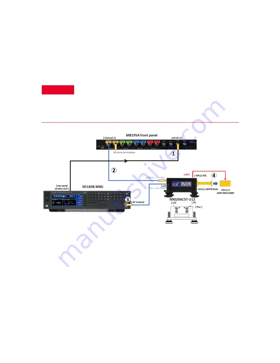
The RF paths cabling and connection are shown in
below.
Figure 2
System RF connection
1
The 10 MHz reference output from the rear panel of the N5183B should be
connected to the
ref clk in
port of the M8195A front panel using a BNC cable
and a BNC to 3.5 mm adaptor.
2
Connect the
Channel 1 Data Out
to the IF input (M) of the
N9029ACST-U12
.
Since the RF output from the M8195A can exceed 0 dBm, an optional 8493C
6 dB attenuator may
be optionally
attached in series to protect the up
converter from accidental damage. The attenuator will also lower the AWG’s
WARNING
The N9029ACST-U12 and other millimeter wave accessories are very
sensitive to damage from high RF power levels. Please ensure that all RF
output from the MXG and M8195A are turned off if the instruments are
already powered up during connection. DC power must be applied to the
N9029ACST-U12 up-converter before any RF power is applied. Likewise, RF
power must be turned off before DC power to the up-converter is removed.
Содержание E8740A-070
Страница 1: ...Keysight E8740A 070 Performance Radar Signal Generation Solution Start up Guide...
Страница 4: ...4 Keysight E8740A 070 Start up Guide THIS PAGE HAS BEEN INTENTIONALLY LEFT BLANK...
Страница 6: ...6 Keysight E8740A 070 Start up Guide THIS PAGE HAS BEEN INTENTIONALLY LEFT BLANK...
Страница 15: ...Keysight E8740A 070 Start up Guide 15 6 You may need to reboot the system after installation...
Страница 50: ...50 Keysight E8740A 070 Start up Guide THIS PAGE HAS BEEN INTENTIONALLY LEFT BLANK...


