KERR KD Gemini Скачать руководство пользователя страница 8

KD GEMINI – INSTALLATION/OPERATION MANUAL 


KD Gemini


May-06 

7

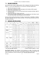
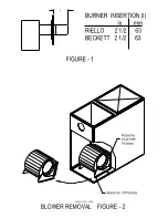
3.8  SET BURNER FOR EFFICIENT OPERATION 


SET END CONE 

Set turbulator to operating decal settings. 


Particularly if you change nozzles.


PUMP PRESSURE    

Refer to “BURNER SPECIFICATIONS” or operating decal. 


BURNER AIR     

Set air damper as settings on operating decal. 


SAMPLING HOLE 

On smoke/vent pipe, between appliance breech and draft 
control, punch or drill a 1/4” round opening. 


Direct Vents have a sampling port located on the breach 
connecting adaptor. 


DRAFT PRESSURE 

Using an accurate draft meter, adjust the draft control to obtain -
0.04” wc draft pressure at the breech sampling hole.  Use two 
barometric dampers if necessary. 


Not applicable to Direct Vent. 


BURNER SETTING 

Set the burner to give a stable symmetrical flame.  After 15 
minutes of normal operation, check SMOKE for #0  – trace 
reading and measure CO

2


Re-adjust the burner controls as 

required.  When the burner is set, lock the adjustments with the 
locking nuts 


EFFICIENCY  

Always leave burner set with CO

2

 reading about 1% lower than 

the peak CO

2

 efficiency achieved with a #0 – trace smoke (e.g. 

a #0  – trace reading of 12.5% CO

2

 should be set back 1% to 

11.5%).  This gives better allowance for fuel and draft variations 
and maintains a better seasonal efficiency.  When the burner is 
set, lock the adjustments with the locking nuts. 


FLAME CHECK


Look through view port to check the flame after setting the 
burner.  If the flame is not clean and symmetrical, reset the 
burner or replace the nozzle, only use nozzle types specified in  
“BURNER SPECIFICATIONS” or operating decal. 


Always set flame with proper draft, smoke and CO2 measurements. 
 

DO NOT


START BURNER UNTIL ALL FITTINGS AND COVERS ARE IN PLACE. 


Содержание KD Gemini

Страница 1: ...AT MAY DIFFER FROM THIS MANUAL Please read this complete manual before beginning installation These instructions must be kept with the furnace for future reference CERTIFIED TO CAN CSA Std B140 0 Std...

Страница 2: ...ement Venting Ventilation 5 3 5 Installation 5 3 6 Assemble Install Burner 6 3 7 Changing Nozzle 6 3 8 Set Up Burner For Efficient Operation 7 3 9 Blower Settings 8 3 10 Cooling AC Models 8 3 11 Humid...

Страница 3: ...se new approved disposable filters of the same size and type or clean permanent filters according to manufacturer s instructions Replace the filters or clean the filters more often if dusty conditions...

Страница 4: ...hat has been shut down for an extended period of time INSPECTION Have the furnace system serviced and inspected by a qualified technician CHECK Furnace system has not been tampered with FUEL ON Turn o...

Страница 5: ...ANY OTHER APPLIANCE 3 3 INSTALLATION CODES INSTALLATION MUST COMPLY WITH THE REQUIREMENTS OF AUTHORITIES HAVING JURISDICTION All local and national codes governing the installation of oil burning equ...

Страница 6: ...g decal for approved vent flue pipe sizes Maximum flue gas temperature is 575 F THROUGH THE This Furnace is approved for Kerr Direct Vent WALL VENTING COMBUSTION Install openings and ductwork to the f...

Страница 7: ...heck for clean seating and tighten in nozzle adaptor CHECK See burner manufacturer s instructions for correct setting ELECTRODES INSERTION See GENERAL SPECIFICATIONS or diagram Figure 1 LENGTH MOUNT B...

Страница 8: ...a stable symmetrical flame After 15 minutes of normal operation check SMOKE for 0 trace reading and measure CO2 Re adjust the burner controls as required When the burner is set lock the adjustments wi...

Страница 9: ...nty 3 12 THERMOSTAT ANTICIPATOR SETTING Thermostat anticipator setting should be 0 2 amps for any burner Check that the thermostat anticipator setting matches the primary control circuit current draw...

Страница 10: ...struction and the heating system tested on a long burn cycle 7 If the block vent switch shuts down the system check to ensure there is enough draft in the chimney and venting pipes 3 14 FAN CONTROL LI...

Страница 11: ...tight as possible Use a pipe joint compound suitable for oil on all pipe threads To reduce possibility of air leaks tighten stem packing gland nut on any valves installed in the suction line Also be s...

Страница 12: ...5 2 84 0 60 60B 3 5 0 0 88 000 26 850 950 4 3 0 92 3 48 0 75 60W 150 5 0 1 5 105 000 31 1080 1200 3 2 KDF R E 115 A3 Riello 40 F3 1 00 3 81 0 75 60W 175 5 0 1 5 116 000 34 1080 1300 3 1 KDF R E 130 A3...

Страница 13: ...2 wc External static AC 0 5 wc Cooling Air Flow 3 tons Maximum air temperature rise 85 F Fan Control 130 F ON 100 F OFF High Limit max design outlet temp 200 F 1 3 hp 1 speed 0 50 static 1300 CFM MOT...

Страница 14: ...fied for use with Kerr Direct Vent Certified for use with Kerr KPV SS1C through the wall mechanical vent system 10 0 TROUBLE SHOOTING GUIDE Furnace will not start Tripped blocked vent switch Clear ven...

Страница 15: ...hrough Change or insulate ductwork Unheated spaces Low speed switch is on Switch off blower low speed FAN OFF set low Fan control Set FAN OFF higher Motor speed set too high Reset motor speed to slow...

Страница 16: ...__________________________ START UP TEST RESULTS Nozzle ________________________________________ Pressure _______________________________________________ Air __________________________________________...

Страница 17: ......

Страница 18: ...KDF 14A Filter Frame Assembly K00 CB 0025 00 KDF 15 Rear Cabinet Top KD KC KD0 CB 0020 00 KDF 16 Blower Door 3BU 10 00DD 00 KDF 17 Delhi GT10 DD Blower 4CA 00 505M 23 KDF 18A Motor Run Capacitor 5 mi...

Страница 19: ......

Страница 20: ...KDR 14A Filter Frame Assembly K00 CB 0024 00 KDR 15 Rear Cabinet Top KD0 CB 0020 00 KDR 16 Blower Door K00 CB 0103 00 KDR 17 5 Flue Pipe Collar 3BU 10 00DD 00 KDR 18 Delhi GT10 DD Blower 4CA 00 505M 2...

Страница 21: ......

Страница 22: ......

Страница 23: ......

Страница 24: ......

Отзывы: