background image

caution


when


installing


the


connecting


rod


assembly


in


the


pump


is


to


make


certain


the


oil


holes


in


the


rod


are


“UP”


and


not


toward


the


bottom


of


the


pump.


This


will


result


in


lubrication


failure


in


these


parts


and


the


pump


will


fail


in


a


short


period


of


time.


An


additionally


important


step


is


to


make


sure


that


the


rod


cap


is


bolted


back


on


the


rod


as


it


came


off.


The


rod


and


cap


carry


a


“mark”


or


“number”


which


allows


you


to


match


them


back


properly.


Failure


to


do


this


will


cause


the


rod


not


to


fit


the


journal


for


which


it


was


made.


H.


Power


End/Fluid


End


Connection:


A


common


misconception


is


that


there


is


some


form


of


fluid


seal


between


the


power


end


and


the


fluid


end.


This


is


false.


The


fluid


end


is


merely


bolted


to


the


power


frame.


It


can


be


removed


by


breaking


the


plunger


connection,


backing


off


the


packing


nut


or


gland,


removing


the


various


fluid


end


bolts,


and


sliding


the


entire


fluid


end


off


the


power


frame.


Corrosion


may


tend


to


seize


the


two


components


together


making


their


separation


difficult


in


some


isolated


cases.


On


models


KP

3300,


KT

3350/KT

3400


and


R335/R340


the


bolted


in


stuffing


box


assemblies


must


be


removed


prior


to


removal


of


the


entire


fluid


end.


They


are


held


in


place


by


four


studs


each.


On


all


other


units


the


stuffing


boxes


can


be


left


intact.


On


the


remaining


pumps


(with


the


exception


KD

1250B,


KJ

2250B,


KM

3250B,


and


KCP

6300)


the


stuffing


boxes


are


held


in


place


in


the


fluid


end


by


a


friction


or


“press”


fit.


They


should


be


removed


with


a


hydraulic


press


if


possible.


These


press

in


type


stuffing


boxes


carry


a


gasket


and/or


an


o

ring


to


insure


a


good


seal.


The


boxes


on


the


KD

1250B,


KJ

2250B,


KM

3250B,


and


KCP

6300


are


screw

in


type


and


carry


only


a


copper


gasket.


Содержание KT-3350XP

Страница 1: ...Corporation Post Office Box 735 2214 West 14th Street Sulphur Oklahoma 73086 Phone 580 622 4207 Fax 580 622 4206 Website www kerrpumps com Email information kerrpumps com United States and Canada 800...

Страница 2: ...hin fifteen 15 days of the date of sale C In the event of a claim under this warranty made within the one year warranty period the purchaser must notify the Distributor and the Distributor shall conta...

Страница 3: ...ive product The responsibility of Kerr Pump Corporation is limited to the repairing or replacing defective material manufactured by it provided Kerr Pump Corporation examination discloses to its satis...

Страница 4: ...correct type of packing for particular installation Contact Kerr Pump Corporation if you are unsure Abnormal wear of fluid end parts Abrasive or corrosive fluid Abnormal wear of power end parts Lack o...

Страница 5: ...discharge line valve and start the pump Roughness may occur from cavitation air in line or from starvation lack of fluid Eliminate these troubles before permitting continuous operation For best resul...

Страница 6: ...E JOINT PAIR SHOULD BE POSITIONED TO MINIMIZE EFFECTS OF PIPING THERMAL EXPANSION CONTRACTION AND PIPING WEIGHT 8 SUCTION SIZED FOR 1 TO 2 FT SEC MAX FLOW RATE DISCHARGED SIZED FOR 8 TO 10 FT SEC MAX...

Страница 7: ...iller cap in kerosene C Check valves for excessive wear broken or bent springs etc D Check crankshaft bearings for endplay See section on crankshaft E Keep all nuts studs etc tight F Check valve cover...

Страница 8: ...DELS A WING GUIDED VALVES i DISCHARGE VALVES The discharge valve and seat can be exposed by first removing the discharge valve cover cap Once the discharge cover cap has been removed you may lift out...

Страница 9: ...ing the valve body the upper portion of the valve is removed by removal of the valve capscrew spring retainer valve spring and valve spacer sleeve The valve seat is then pulled from the fluid end util...

Страница 10: ...should be replaced There is no value in constantly re tightening leaking packing If your pump is equipped with optional spring loaded packing there is no adjustment in this equipment during its opera...

Страница 11: ...p and down the main axis of the connecting rod This looseness in the wrist pin fit is the most probable cause of knocking which is traceable to the power end of most all pumps The only solution for lo...

Страница 12: ...removed by breaking the plunger connection backing off the packing nut or gland removing the various fluid end bolts and sliding the entire fluid end off the power frame Corrosion may tend to seize th...

Страница 13: ...ating deterioration or contamination by moisture 3 0 PRESERVATIVE PRODUCT 3 1 The specified rust preservative will protect the internal power end parts from corrosion due to atmospheric moisture and m...

Страница 14: ...arty inspection will be signed off by the purchaser or customer representative prior to final crating and shipment 4 2 2 Export crating will be performed by either an approved Kerr Pump source or as s...

Страница 15: ...to prevent preventative deterioration or contamination by moisture 3 0 RUST PREVENTATIVE PRODUCT 3 1 The recommended rust preservative should protect the internal power end parts from corrosion due t...

Страница 16: ...Any witnessed or third party inspection will be signed off by the purchaser or customer representative prior to final crating and shipment 4 2 2 Export crating will be performed by either an approved...

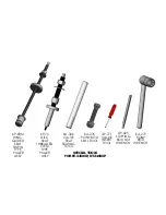
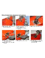
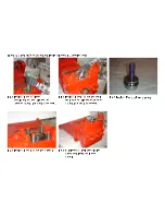
Страница 17: ...XP KT 3400XP PULLER AP 425 BOX NUT STUFFING WRENCH TRI PIN TYPE KP 68M WING GUIDED KA 306 VALVE SEAT SEATING TOOL AP 77T VALVE INSERT TOOL KA 276 PONY ROD SEAL TOOL KA 277 PONY ROD WRENCH KP 75 DISC S...

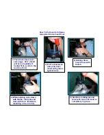
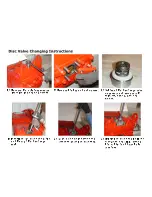
Страница 18: ...e insert with groove against valve 4 While holding valve down with thumb rotate around valve with tool Similar to mounting a tire on a rim 1 Push Valve Insert over valve legs Hint Insert will be more...

Страница 19: ......

Страница 20: ...4 5 2 4 2 0 8 9 2 8 2 4 5 2 4 2 2 9 2 1 5 2 1 3 4 4 3 0 4 0 A B 5 2 4 5 5 8 4 5 2 1 4 2 4 2 2 4 0 0 0 C 5 D 4 0 E 9 3 4 0 1 4 F 5 5 0 2 4 5 5 1 4 2 0 2 5 D 4 0 C 0 0 G 4 F 8 5 0 1 5 2 D D H 2 I J D K...

Страница 21: ...X V a e Y T Y V U V S _ V W _ Y P a _ Y S b a c W d Z T S e f V a V S X V c c Y a P N h P Q R S T U V W W U X Y T Z U S T i a S e P N j P Q R S T U V W W U X Y T X V a e Y T i a S e P N k P Q l e X U...

Страница 22: ......

Страница 23: ...8 B C 2 3 9 3 C A 9 8 J K L M N O P Q R P K S T U V R W T X Y T S S K Z Q W S K R U R U U Q Q X X Q Q X Q W _ K U E E G 0 2 9 2 3 4 4 4 4 5 8 0 1 8 4 2 9 0 4 8 9 0 9 5 8 4 C 1 3 2 4 0 2 2 3 4 5 4 I 4...

Страница 24: ...KA 26G KA 28S GLAND GASKET KA 26 PONY ROD KA 28 SEALS KA 26 A PONY ROD PACKING GLAND ASSEMBLY...

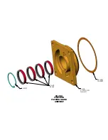
Страница 25: ...T OF THREE ONLY REMOVED INNER ORING UPDATED PART NUMBERS REV B 03 31 2009 ITEM NO PART NUMBER DESCRIPTION QTY 1 KT 86SL 225GE DSL STUFFING BOX DSL 1 2 KP 95 225S PACKING SPRING SHORT 1 3 KT 60XPAB STU...

Страница 26: ......

Страница 27: ...062 17 75 1 1 4 125 3 03 9 35 8 500 HOLES 4X 11 16 MOUNT 2 NPT 16 00 6 2 GENERAL DIMENSIONS FOR KT 3350XP KT 3400XP 2 15 16 KEYWAY 3 4 X 3 8 29 3 42 98 17 0 DISCHARGE 2 3 SUCTION 8 00 32 437 2 875 5 5...

Страница 28: ...NUT STUFFING STUFFING BOX SL ORING KA 54 PACKING KP 95 225S SPRING SHORT KT 60XP KP 93SL KM 88V PACKING SET KP 93SL TOP ADAPTER PEAK PACKING ARRANGEMENT SHOWN IN KT 86SL STUFFING BOX KP 300SSAR KP 85...

Страница 29: ...e KT 8 010 400 Main Bearing Adjusting Shims 010 as require KT 8 005 400 Main Bearing Adjusting Shims 005 as require KT 8 005 Main Bearing Adjusting Shims 005 as require KT 9 Main Bearings 2 KT 10 Pan...

Страница 30: ...End Cover Cap Bolted AB 3 KP 32N Cover Cap O Ring Nitrile 6 KP 32A Cover Cap O Ring Aflas 6 KA 32 Pony Rod Splash Guard 3 KT 33XPSS Fluid End Vessel Only Stainless Steel 1 KT 33XPS Fluid End Vessel O...

Страница 31: ...ger Chamber Cover Standard 1 KT 64L Plunger Chamber Cover Standard Lube System 1 KP 66V 0758 225 Pressure Rings 758 SF 2 1 4 3 sets KP 66V 0805 225 Pressure Rings 805 SF 2 1 4 3 sets KP 67V 0758 200 P...

Страница 32: ...sets KM 88V 0805 175 Pressure Rings 805 SF 1 3 4 3 sets KP 93SL 150 Adapters SF Packing 3 KP 93SL 225AB Adapters SF Packing AB 3 KP 93SL 200AB Adapter SF Packing AB 3 KP 93SL 175 Adapters SF Packing 3...

Страница 33: ...KP 82ARSS KT 52L SS 3 KP 300AB Discharge Valve Assy Complete KP 43 KP 45 KT 52L AB 3 KP 305SS Suction Valve Complete KP 50 KP 51 KT 52S SS 3 KP 305M Suction Valve Complete KP 47 KP 48 KT 52S Monel 3 K...

Страница 34: ...Part Number Description Req KT 800 225 Kerramic Plungers 2 1 4 3 KT 800 200 Kerramic Plungers 2 3 KT 800 150 Kerramic Plungers 1 1 2 3 KT 800 175 Kerramic Plungers 1 3 4 3 All prices and part numbers...

Отзывы: