G.
DISASSEMBLY
OF
POWER
END
CAUTION
:
Prior
to
disassembly
of
any
power
end,
the
plunger,
pony
rod,
and
pony
rod
seal
housing
must
be
removed.
Expose
the
crankshaft
and
connecting
rods
by
removing
the
pan
cover.
Connecting
rod
caps
may
now
be
removed
and
the
connecting
rod
and
crosshead
should
be
shoved
all
the
way
to
the
rear
(toward
the
fluid
end)
to
facilitate
crankshaft
removal
out
either
side
as
convenient.
The
connecting
rods
and
crossheads
may
now
be
taken
out
the
front
cavity
exposed
by
removing
the
crankshaft.
Connecting
rods
may
be
removed
from
the
crosshead
by
loosening
the
setscrew
and
driving
out
the
wrist
pin
from
the
crosshead.
A
bronze
bushing
is
used
in
the
rod
it
may
be
driven
out
of
the
rod
and
replaced
with
a
new
bushing.
Reassembly
is
the
reverse
of
the
above
outlined
sequence
with
the
following
considerations
for
“fits”
or
tolerance:
i.
General:
All
Kerr
components
are
machined
on
modern
production
machine
tools
and
are
of
the
same
specifications
and
close
tolerances
you
would
expect
in
a
modern
automobile
engine.
It
must
be
pointed
out
that
at
top
speed
(350
to
400
RPM)
your
pump
will
not
even
be
approaching
idle
speed
for
a
gasoline
engine
so
“field
fits”
are
possible
and
practical
when
making
repairs
and
replacements
away
from
the
factory.
All
procedures
outlined
below
are
possible
with
only
hand
tools
and
absolutely
no
instruments,
special
tools,
or
gauges
are
needed.
ii.
Connecting
rod
and
wrist
pin:
Proper
fit
will
find
the
wrist
pin
turning
freely
in
its
bore
in
the
connecting
rod,
but
it
should
have
no
“wobble”
that
is
discernable
up
and
down
the
main
axis
of
the
connecting
rod.
This
looseness
in
the
wrist
pin
fit
is
the
most
probable
cause
of
“knocking”
which
is
traceable
to
the
power
end
of
most
all
pumps.
The
only
solution
for
loose
fitting
wrist
pins
is
to
discard
the
connecting
rod
wrist
pin
bushing
and
replace
with
a
new
one.
If
any
wear
is
visible
on
the
wrist
pin
it
should
always
be
replaced.
iii.
Crankshaft
End
Play
and
Lateral
adjustments:
Adjustment
of
the
Taper
Roller
bearings
used
in
all
Kerr
Pumps
is
accomplished
by
removing
or
adding
shims
under
the
bearing
housing.
Shims
are
taken
out
or
added
until
the
crankshaft
(without
connecting
rods)
will
turn
freely,
but
with
no
endplay
felt
when
attempting
to
pull
or
push
the
jackshaft
end
of
the
crankshaft
along
its
long
axis.
Some
lateral
adjustment
is
possible
by
removing
shims
from
one
side
of
the
crankshaft
and
adding
them
to
the
opposite
side.
(Note:
Lateral
adjustment
is
the
“centering”
of
the
crankshaft
in
the
power
frame
housing.)
iv.
Connecting
Rod
to
Crankshaft
fitting:
Factory
bored
connecting
rods
will
normally
fit
the
standard
crankshaft
journal
just
by
bolting
the
cap
on
the
rod
with
the
standard
rod
shims
being
used.
If
the
caps
do
require
adjustment
this
is
accomplished
by
removing
or
adding
various
thicknesses
of
rod
shims.
The
standard
connecting
rod
shim
used
on
all
Kerr
Pumps
is
1/32”
thick
and
is
comprised
of
.002”
laminates,
which
can
be
“pealed
“
off
separately.
Proper
fit
of
the
connecting
rod
will
allow
the
pump
crankshaft
to
be
rotated
while
not
allowing
in
‐
and
‐
out
slack
in
the
connecting
rod
along
its
long
or
main
axis.
A
well
‐
fitted
rod
will
have
none
of
the
in
‐
and
‐
out
slack,
but
should
be
free
enough
to
be
moved
from
side
to
side
on
the
rod
journal.
This
insures
the
rod
not
being
too
tight.
A
point
of
Содержание KT-3350XP
Страница 19: ......
Страница 22: ......
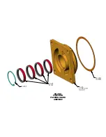
Страница 24: ...KA 26G KA 28S GLAND GASKET KA 26 PONY ROD KA 28 SEALS KA 26 A PONY ROD PACKING GLAND ASSEMBLY...
Страница 26: ......


