background image

X-band 12kW Upmast Magnetron Transceiver 

Chapter 4: Typical system 

HBK-2300-3 Issue 2 

Page 12 of 40


Page Intentionally blank 


Содержание X-band

Страница 1: ...KELVIN HUGHES X band 12kW UPMAST TRANSCEIVER INSTALLATION INSTRUCTIONS HBK 2300 3 Issue 2 SITUATIONAL INTELLIGENCE THE WORLD OVER ...

Страница 2: ...r Date inserted DD MM YYYY Initials Equipment modification number Copyright Kelvin Hughes 2016 limited all rights reserved Printed copies of this document are unmaintained No parts of this publication may be reproduced transmitted transcribed translated or stored in any form or by any means without the written permission of Kelvin Hughes Limited Technical details contained in this publication are ...

Страница 3: ...1 Transceiver 19 5 5 2 Mounting hole dimensions 20 5 5 3 E70352 DC Power Unit 21 5 6 Compass safe distances 21 6 Cabling guidance 23 6 1 General advice 23 6 2 Grounding 24 7 CONNECTION DETAILS 25 7 1 Transceiver 25 7 2 Longer LAN cable 25 7 3 Power Supply 26 7 4 Breaker and fuse ratings 27 8 Setting to work 29 8 1 Radar scanner initial power on test 29 8 2 Radar checks 29 8 3 Check and adjust bear...

Страница 4: ...X band 12kW Upmast Magnetron Transceiver Chapter 1 Contents HBK 2300 3 Issue 2 Page 4 of 40 Page Intentionally blank ...

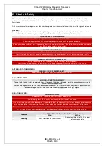
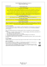
Страница 5: ...FF before starting to install this product Do NOT connect or disconnect the equipment with the power switched ON unless instructed in this document ANTENNA ROTATION WARNING WARNING RADAR SCANNER SAFETY Before rotating the radar scanner ensure all personnel are clear EQUIPMENT ACCESS NOTICE ACCESS TO EQUIPMENT To meet with electrical safety recommendations all equipment should be situated in a rest...

Страница 6: ...in snow ice or if access is required at sea risk of vessel pitch and roll ANTI STATIC HANDLING Certain semiconductor devices used in the equipment are liable to damage due to static voltage Persons removing sub units from equipment containing these devices must be earthed by a wrist strap and a resistor at the labelled point provided on within the equipment Observe the following precautions when h...

Страница 7: ...ate personal protective equipment PPE must be worn Where special equipment such as cranes hoists and jigs is required consideration must be given to the authority to use such equipment During lifting a safety zone shall be established beneath the lifting area around any cranes or platforms Safety personnel must ensure that persons do not encroach on the area of work Consult with the lifting operat...

Страница 8: ...X band 12kW Upmast Magnetron Transceiver Chapter 2 Health Safety HBK 2300 3 Issue 2 Page 8 of 40 Page Intentionally blank ...

Страница 9: ...driver Pozidrive head 5 Adhesive tape 6 11 mm drill bit 7 3 mm drill bit 8 17 mm spanner 9 13 mm spanner 10 Torque wrench 3 2 Fitting kit contents Item Description Qty 1 Pedestal 1 2 Mounting template 1 3 Denso paste 1 4 E70352 Voltage Converter 1 5 E70352 cable clamp 1 6 Lifting eye 3 7 Stud 4 8 Plain Washer 4 9 Spring washer 4 10 Nut 8 11 E70352 mounting screw 2 12 E70352 cable clamp mounting sc...

Страница 10: ...als e g VHF radios cables and antennas In the case of SSB radios the distance should be increased to 2m More than 2 m from the path of a radar beam A radar beam can normally be assumed to spread 20 degrees above and below the radiating element The cables supplied and specified for the equipment are correctly fitted and used Cables are not cut or extended unless doing so is detailed in the installa...

Страница 11: ...X band 12kW Upmast Magnetron Transceiver Chapter 4 Typical system HBK 2300 3 Issue 2 Page 11 of 40 4 Typical system ...

Страница 12: ...X band 12kW Upmast Magnetron Transceiver Chapter 4 Typical system HBK 2300 3 Issue 2 Page 12 of 40 Page Intentionally blank ...

Страница 13: ...truction there will be a reduction of the beam intensity There may be a blind sector if the beam intensity is not sufficient to obtain an echo from an object This may occur even at close range For this reason the angular width and relative bearing of any shadow area must be determined at installation You may be able to detect shadow areas or false echoes on your multifunction display For example s...

Страница 14: ...de a crane hoist or an appropriate rigid overhead structure WARNING DO NOT LIFT THE TRANSCEIVER WITH THE ANTENNA FITTED NOTICE DO NOT connect any cables until the following steps have been completed 1 Check the selected location A clear flat platform is required for mounting the pedestal unit 2 Fix the supplied mounting template to the platform using masking or self adhesive tape 3 Using a 3mm dri...

Страница 15: ...ting surface Carefully lower into position taking care that the studs pass through the holes without damaging the threads Ensure that the front of the pedestal is pointing towards the bow of the vessel 11 Grease the studs with the supplied Denso paste 12 Use the 4 nuts and associated washers to secure the pedestal to the platform Ensure all 4 sets of nuts and washers are used to secure the pedesta...

Страница 16: ... until you are ready to fit antenna to the pedestal unit The pedestal power switch is in the OFF position 1 Fit the 4 threaded alignment guides to the studs on the underside of the antenna 2 Ensure a close fit The alignment guides are essential to help prevent damage to the coaxial pin 3 Remove the protective cap from the antenna shaft Retain the cap for future use 4 Position the antenna mounting ...

Страница 17: ...nted in a location which allows proper routing and connection of cables Minimum bend radius of 100 mm 3 94 in unless otherwise stated Use cable supports to prevent stress on connectors The maximum length of cable between the DC power source and the E70352 should not normally exceed 6m All power cable lengths should be kept as short as possible See section 7 3 for additional details WATER INGRESS T...

Страница 18: ...ing area inside the mounting lug on each side of the E70352 unit 4 Using a 3 mm drill bit drill a hole through the pencil marks 5 Align the E70352 mounting lugs with the drill holes 6 Hold the E70352 in place 7 Using a suitable screwdriver screw the self tapping mounting screws through the mounting lug holes into the drilled holes 8 Connect the cables according to the instructions provided in this...

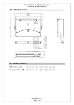
Страница 19: ...Magnetron Transceiver Chapter 5 Mechanical installation HBK 2300 3 Issue 2 Page 19 of 40 5 5 DIMENSIONS 5 5 1 Transceiver V M 1 16 05 2016 A1 1 KELVIN HUGHES X BAND 12kW UPMAST TRANSCEIVER RYM E70351 RYM E70350 V M REL SD ...

Страница 20: ...X band 12kW Upmast Magnetron Transceiver Chapter 5 Mechanical installation HBK 2300 3 Issue 2 Page 20 of 40 5 5 2 Mounting hole dimensions Note A drilling template is provided as part of the fitting kit ...

Страница 21: ...Mechanical installation HBK 2300 3 Issue 2 Page 21 of 40 5 5 3 E70352 DC Power Unit 5 6 Compass safe distances E70352 Power supply Mount at least 1 0m away from a magnetic compass Transceiver scanner unit Mount at least 1 0m away from a magnetic compass ...

Страница 22: ...X band 12kW Upmast Magnetron Transceiver Chapter 5 Mechanical installation HBK 2300 3 Issue 2 Page 22 of 40 Page Intentionally blank ...

Страница 23: ...ife Do NOT bend cables excessively Wherever possible ensure a minimum bend radius of 100 mm Protect all cables from physical damage and exposure to heat Use trunking or conduit where possible Do NOT run cables through bilges or doorways or close to moving or hot objects Secure cables in place using tie wraps or lacing twine Coil any extra cable and tie it out of the way Where a cable passes throug...

Страница 24: ...r braid with a 30 A rating 1 4 inch or greater In any grounding system always keep the length of connecting braid or wires as short as possible CONDUCTIVITY TESTS During installation and maintenance the earth connections must be tested for conductivity using a high current impedance meter such as a Megger or similar WRIST STRAPS Fully isolate and mechanically disconnect all sources of AC before at...

Страница 25: ...o the positive POWER OUT terminal of the E70352 2 BLACK WIRE Connect to the negative POWER OUT terminal of the E70352 3 SCREEN STRANDS Connect to one of the SCREEN terminals of the E70352 CAUTION The standard cable must not be cut shortened or lengthened TRANSCEIVER CONNECTOR The power and data connector is at the rear of the radar scanner unit Ensuring that the arrow on the power and data cable c...

Страница 26: ... and that the connection is of a very low resistance as considerable power passes through this connection The following table provides recommended total power cable lengths and gauges These figures relate to the maximum distance of power cables from the ships DC supply or optional AC DC power supply to the E70352 CAUTION Exceeding the following cable lengths may cause unreliable operation AWG Amer...

Страница 27: ...stem 5 POWER IN positive connect to the positive terminal of the DC distribution panel or battery isolator switch 6 POWER IN negative connect to the negative battery terminal 7 Not used in this application 8 Not used in this application 9 Not used in this application 7 4 Breaker and fuse ratings All power connections between the E70352 and its power source must be protected by a thermal circuit br...

Страница 28: ...X band 12kW Upmast Magnetron Transceiver Chapter 7 CONNECTION DETAILS HBK 2300 3 Issue 2 Page 28 of 40 Page Intentionally blank ...

Страница 29: ... ON the magnetron warm up sequence should start after which the transceiver should enter Standby mode 8 2 Radar checks WARNING RADAR SCANNER SAFETY Before rotating the radar scanner ensure all personnel are clear WARNING RADAR TRANSMISSION SAFETY The radar scanner transmits electromagnetic energy ensure all personnel are clear of the scanner when the radar is transmitting 1 From the display sub sy...

Страница 30: ...e of misaligned radar CONFIGURATION APP The bearing and antenna parking alignment is configured using a stand alone application The APP is delivered as a software bundle with the Kelvin Hughes Navigation Display The configuration is carried out on the installation engineer s laptop when it is connected to the MDC A201 1 Managed network Switch The setup is carried out as part of the display to tran...

Страница 31: ...Problem with the power supply Check relevant fuses breakers Check that the power supply cable is sound and that all connections are tight and free from corrosion Check that the power source is of the correct voltage and sufficient current RADAR TROUBLESHOOTING Problems with the radar and their possible causes and solutions are described here Problem Possible causes Possible solutions No Data or No...

Страница 32: ...X band 12kW Upmast Magnetron Transceiver Chapter 8 Setting to work HBK 2300 3 Issue 2 Page 32 of 40 Page Intentionally blank ...

Страница 33: ...on Standby 30 watts Power consumption sleep 1 2 watts Warm up time 75 seconds Environmental Waterproof rating IPX6 Operating temperature range 25 C to 55 C Humidity Up to 40 C at 95 relative humidity Maximum wind speed Starts in winds up to 100Kn Transmitter Frequency 9405 MHz 20 MHz Peak output power 12kW Receiver Intermediate frequency 75MHz Receiver characteristics Linear Antenna Beamwidth vert...

Страница 34: ...X band 12kW Upmast Magnetron Transceiver Chapter 9 Specification HBK 2300 3 Issue 2 Page 34 of 40 Page Intentionally blank ...

Страница 35: ...mpartment of suitable size It is important to check the unit s location to ensure it is correctly mounted and that all fastenings are secure and tightened Make sure that the device will not be affected by electromagnetic field generators The chosen location should not be an area of high vibration The area should be free of dust The device should not be left in direct sunlight 10 2 Grounding The un...

Страница 36: ...24V DC 170W Operating temperature range 15 C to 55 C 93 relative humidity Storage temperature 20 C to 70 C 93 relative humidity Power supply wires 110V AC 2 X 1 5mm2 220V AC 2 X 0 7mm2 24V AC 2 X 6 0mm2 Note The Absolute maximum voltage allowed on the battery input is 32V Weight 5kg 10 5 Operation There are no operator functions or controls apart from the ON OFF switch on the outside of the device...

Страница 37: ...pares email spares kelvinhughes co uk Phone 44 0 1992 805 301 Internet Website www kelvinhughes com KELVIN HUGHES REGIONAL OFFICES A full list of regional offices and authorised service agents is also available on the Kelvin Hughes website Kelvin Hughes Rotterdam Netherlands BV service kelvinhughes nl Phone 31 10 472 4050 Fax 31 10 472 4051 Kelvin Hughes A S Bergen Norway service kelvinhughes dk P...

Страница 38: ...X band 12kW Upmast Magnetron Transceiver Chapter 11 Contacting Kelvin Hughes HBK 2300 3 Issue 2 Page 38 of 40 Notes page 1 of 2 ...

Страница 39: ...X band 12kW Upmast Magnetron Transceiver Chapter 11 Contacting Kelvin Hughes HBK 2300 3 Issue 2 Page 39 of 40 Notes page 1 of 2 ...

Страница 40: ...Kelvin Hughes Ltd Limited Voltage 6 Mollison Avenue Enfield EN3 7QX United Kingdom Tel 44 0 1992 805200 Fax 44 0 1992 805310 www kelvinhughes com SITUATIONAL INTELLIGENCE THE WORLD OVER ...

Отзывы: