X-band 12kW Upmast Magnetron Transceiver
Chapter 5: Mechanical installation
HBK-2300-3 Issue 2
Page 17 of 40
5.4
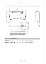
E70352 Power supply
CAUTION
This product is NOT approved for use in hazardous/ flammable atmospheres such as in an engine
room or near fuel tanks.
POWER SUPPLY LOCATION REQUIREMENTS
The E70352 is designed to be internally bulkhead mounted on a flat vertical surface.
VENTILATION
Ensure that equipment is mounted in a compartment of suitable size.
Ensure that ventilation holes are not obstructed.
Allow adequate separation between equipment.
CABLES
Ensure the unit is mounted in a location which allows proper routing and connection of cables:
Minimum bend radius of 100 mm (3.94 in) unless otherwise stated.
Use cable supports to prevent stress on connectors.
The maximum length of cable between the DC power source and the E70352 should not
normally exceed 6m.
All power cable lengths should be kept as short as possible.
See section 7.3 for additional details.
WATER INGRESS
The E70352 is splash proof and suitable for internal mounting below decks only.
ELECTRICAL INTERFACE
Select a location that is far enough away from devices that may cause interference, such as motors,
generators and radio transmitters/ receivers.
POWER SUPPLY
Select a location that is as close as possible to the vessels DC power source. This will help to keep
cable runs to a minimum.


