


Chapter 4
28
89
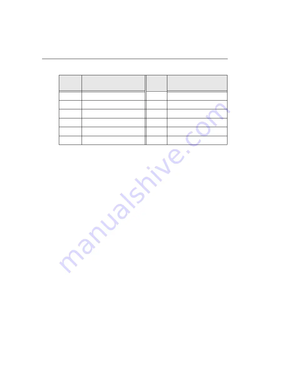
Bank 10, Bit 6
90
Bank 10, Bit 7
91
Bank 11, Bit 0
92
Bank 11, Bit 1
93
Bank 11, Bit 2
94
Bank 11, Bit 3
95
Bank 11, Bit 4
96
Bank 11, Bit 5
97
Bank 11, Bit 6
98
Bank 11, Bit 7
99
Is5 V
100
Isolated Ground
a. Dedicated digital input only. The KUSB-3160 module can generate a PCI-bus interrupt when
any of the digital input lines (bits) corresponding to banks 10 and 11 changes state.
Table 2: Pin Assignments for Connector J1 (cont.)
Pin
Number
Signal Description
Pin
Number
Signal Description
Содержание KUSB-3160
Страница 12: ...About this Manual xii ...
Страница 13: ...1 1 Overview Key Hardware Features 2 Software 3 Accessories 4 Getting Started Procedure 5 ...
Страница 18: ...Chapter 1 6 ...
Страница 19: ...7 2 Preparing to Use a Module Unpacking 9 Checking the System Requirements 10 Installing the Software 11 ...
Страница 24: ...Chapter 2 12 ...
Страница 34: ...Chapter 3 22 ...
Страница 35: ...23 4 Wiring Signals Attaching the Screw Terminal Panel 25 Preparing to Wire Signals 35 ...
Страница 50: ...Chapter 4 38 ...
Страница 51: ...39 5 Verifying the Operation of a Module Overview 41 Running the Quick Data Acq Application 42 ...


