


GB - 31
Parameter Description
6.
Parameter Description
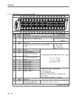
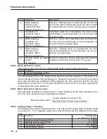
On delivery the KEB COMBIVERT G6 is assigned with an user menu, the CP-Parameters.
These parameters describe a selection of the most important inverter functions. If required up
to maximally 48 CP-Parameters can be defined.
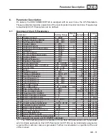
6.1
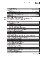
Overview of the CP-Parameters
Parameter
Setting Range Resolu-
tion Default Unit
↵
based
on
CP.0 Password input
0…9999
1
- -
-
ud.1
CP.1 Actual frequency display
-400…400
0.0125
0 Hz -
ru.3
CP.2 Set frequency display
-400…400
0.0125
0 Hz -
ru.1
CP.3 Inverter status
0…255
1
0 -
-
ru.0
CP.4 Apparent current
0…6553.5
0.1
0 A -
ru.15
CP.5 Apparent current peak value
0…6553.5
0.1
0 A -
ru.16
CP.6 Utilization
0…65535
1
0 % -
ru.13
CP.7 DC link voltage
0…1000
1
0 V -
ru.18
CP.8 DC link voltage peak value
0…1000
1
0 V -
ru.19
CP.9 Output voltage
0…778
1
0 V -
ru.20
CP.10 Minimal frequency
0…400
0.0125
0 Hz -
oP.6
CP.11 Maximum frequency
0…400
0.0125
70 Hz - oP.10
CP.12 Acceleration time
0.00…300.00
0.01
5 s - oP.28
CP.13 Deceleration time (-1=CP.12)
-0.01…300.00
0.01
5 s - oP.30
CP.14 S-curve time
0,00…5,00
0.01
0 s - oP.32
CP.15 Boost
0.0…25.5
0.1
LTK % -
uF.1
CP.16 Rated frequency
0…400
0.0125
50 Hz -
uF.0
CP.17 Voltage stabilization
0…649 V, oFF
1
off V E
uF.9
CP.18 Switching frequency
0…LTK
1
LTK - E uF.11
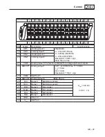
CP.19 Fixed frequency 1
-400…400
0.0125
5 Hz - op.21
CP.20 Fixed frequency 2
-400…400
0.0125
50 Hz - op.22
CP.21 Fixed frequency 3
-400…400
0.0125
70 Hz - op.23
CP.22 DC braking mode
0…9
1
7 - E Pn.28
CP.23 DC braking time
0.00…100.00
0.01
10 s - Pn.30
CP.24 Max. ramp current
0…200
1
140 % - Pn.24
CP.25 Max. constant current
0…200
1 200:off % - Pn.20
CP.26 Speed search condition
0…15
1
8 - E Pn.26
CP.27 Motor protection response
0…6
1
6 – – Pn.14
CP.28 Motor protection mode
0…1
1
1 – –
dr.11
CP.29 Motor protection rated current
0.0…370.0
0.1
LTK A –
dr.12
CP.30 Analog output function
0…26
1
2 – E an.31
CP.31
Analog output amplification
-20.00…20.00
0.01
1 – – an.33
CP.32 Transistor output function
0…86
1
20 – E do.00
CP.33 Relay output function
0…86
1
4 – E do.02
CP.34 Relay output switching level
±30000.00
0.01 100.00 – – Le.02
CP.35 Set value selection
0…2
1
0 – E An.00
CP.36 Select 50/60Hz mode
0…1
1
0 – E ud.06
CP.37 Response to external overtemperature 0…7
1
7 -
- Pn.12
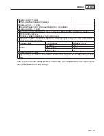
LTK=depending on power unit; E=ENTER parameter
1) The CP-Parameter group is a selection of more than 500 parameters and 8 parameter
sets for simple applications. Each CP-Parameter (not CP.00) can be individually assigned so
a special final customer menue is generated. Further documentation is specified at the end
of this manual.
Содержание COMBIVERT G6 series
Страница 1: ...C O M B I V E R T Mat No Rev 00G6NEM DC00 1G GB Installation Manual Housing C Power 5 5 11kW...
Страница 2: ......
Страница 4: ...GB 4 Table of Contents...
Страница 37: ...GB 37 Parameter Description...
Страница 41: ...GB 41 Notes...