


GB - 17
Connection of the Power Unit
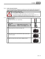
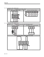
3.2.1.5 Connection at DC voltage supply
Picture 3.2.1.5
Connection at DC voltage supply
- -
U
V
W
PE
PE
T1 T2
++
+U
-U
1
DC voltage
420…746 V DC
2
Fuses
Type aR
Pay attention to the permissible voltage range !
3
KEB COMBIVERT
G6-C
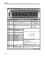
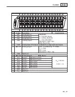
3.2.1.6 Terminal strip X1B
Picture 3.2.1.5
Description of the terminal strip X1B
X1B
Name Function
Cross-section
Tightening
torque
++, – – DC connection
0.2-16 mm²
AWG 26-6
2.3 Nm
20.5 lb-inch
PE,
Connection for
shielding/
earthing
Screw M4 for
ring thimble
1,3 Nm
11 lb inch
3.2.1.7 Conductor cross-section at DC voltage supply
Size
Recommended minimum cross section at rated power.
13
2 x 4 mm²
14
15
2 x 6 mm²
3.2.2 Connection of the motor
3.2.2.1 Selection of the motor cable
The correct cabling as well as the motor cable play an important part in case of low power
in connection with long motor line lengths. Ferrite cores and low-capacitance cable (phase/
phase<65 pF/m, phase/screen < 120 pF/m) at the output have the following effects:
•
longer motor line lengths
•
less abrasion of the motor gearbox by leakage currents
•
better EMC properties
3.2.2.2 Motor line length at operation with DC voltage
The maximum motor line length at DC operation is basically dependent on the capacity of the
motor cable. The internal filter is not active at DC operation. External measures must be taken
here, if necessary. The following data apply for operation under nominal rating conditions.
Содержание COMBIVERT G6 series
Страница 1: ...C O M B I V E R T Mat No Rev 00G6NEM DC00 1G GB Installation Manual Housing C Power 5 5 11kW...
Страница 2: ......
Страница 4: ...GB 4 Table of Contents...
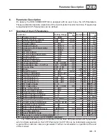
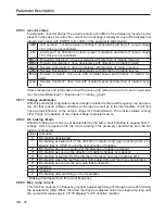
Страница 37: ...GB 37 Parameter Description...
Страница 41: ...GB 41 Notes...