KEB COMBIVERT G6 series Скачать руководство пользователя страница 22

GB - 22

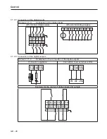
Connection of the Power Unit

Depending on the case of application (e.g. no generatoric operation) simple circuits 

can be used. See chapter 7 for instructions of the download. Input I1 must be program-

med and inverted in the application mode to "external error".

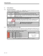
3.2.6  Final test informations of the machines/systems which are provided with frequency 

inverters according to EN 60204 Part 1 of 2007

3.2.6.1  Voltage test (chapter 18.4)

Testing with 1000 Vac (or higher) may not be executed because it would destroy the 

unit.

Permissible: 

If a voltage test shall be done the inverter may be disconnected for this, since a voltage test 

with 2180 Vdc according to EN 61800-5-1 is done ex factory.

3.2.6.2  Isolation resistance measurement (chapter 18.3)

An isolation resistance measurement is permissible, if all power unit connections (grid-con-

nected potential) and control connections are bridged each with PE (R > 2 MΩ). 

Содержание COMBIVERT G6 series

Страница 1: ...C O M B I V E R T Mat No Rev 00G6NEM DC00 1G GB Installation Manual Housing C Power 5 5 11kW...

Страница 2: ......

Страница 3: ...1B 19 3 2 3 2 Wiring of an intrinsically safe braking resistor 19 3 2 4 Connection of a temperature detection 20 3 2 4 1 Temperature detection terminals T1 T2 20 3 2 4 2 Terminal strip X1C temperature...

Страница 4: ...GB 4 Table of Contents...

Страница 5: ...bservance of the safety instructions leads to the loss of any liability claims This list is not exhaustive 1 2 Validity and liability The use of our units in the target products is outside of our cont...

Страница 6: ...f KEB are developed and dimensioned for the use in industrial products If the KEB COMBIVERT F5 is used in machines which work under exceptional conditions or if essential functions life supporting mea...

Страница 7: ...150 3 16kHz 125 150 4 2kHz 150 180 5 4kHz 150 180 6 8kHz 150 180 7 16kHz 150 180 8 2kHz 180 216 9 4kHz 180 216 A 8kHz 180 216 B 2kHz 180 216 Voltage connection 3 3 phase 400V AC DC A Z Customer speci...

Страница 8: ...tinent docu mentation The drive converters shall be protected against excessive strains In particular no components must be bent or iso lating distances altered in the course of transportation or hand...

Страница 9: ...emperature EN60721 3 2 2K3 Humidity 2K3 without condensation Mechanical Vibration 2M1 15m s 200 500Hz Surge 2M1 50g 30ms drop from 0 25m height Contamination Gas 2C2 Solids 2S2 Ambient conditions for...

Страница 10: ...fs 8kHz Time out at cyclic switching at the input min 5 1 The values refer percentage to the output rated current IN 2 The output frequency is to be limited in such a way that it does not exceed 1 10...

Страница 11: ...40 160 180 200 220 fd 6Hz f0 0Hz fA Hz IN HSR 13 14 G6 OC 15 G6 IN OC 13 14 G6 HSR 15 G6 14 G6 8 kHz 15 G6 8 kHz 15 G6 4 kHz 13 G6 16 kHz 13 G6 4 8kHz 14 G6 4kHz Overload characteristic 30 60 90 120 1...

Страница 12: ...GB 12 Mechanical Installation 2 3 Mechanical installation 2 3 2 Dimensions and weights 242 5 2 5 100 117 260 f r M5 230 8 230 Housing C Weight kg 4 6...

Страница 13: ...on Distance in mm Distance in inch C A B D D A 150 6 B 100 4 C 30 1 2 D 0 0 X 1 50 2 1 Distance to preceding elements in the cabinet door If construction conditioned the control cabinet cannot be wit...

Страница 14: ...istor and DC supply 2 X4A Diagnostic interface RS232 485 interface with DIN66019 II 3 X2B Safety function here with STO interface 4 X2A Control terminal strip 32 pole cage clamp terminal strip 5 X1B M...

Страница 15: ...egenerative operation also during mains power failure Therefore a dangerous high tension can exist in the unit after switching off the supply system Before working with the unit check the isolation fr...

Страница 16: ...ctor 4 Mains choke optional 13 14 15Z1B04 1000 5 KEB COMBIVERT G6 C 3 2 1 3 Line terminal strip X1A Picture 3 2 1 1 Description of the line terminal strip X1A X1A Name Function Cross section Tightenin...

Страница 17: ...tion at rated power 13 2 x 4mm 14 15 2 x 6mm 3 2 2 Connection of the motor 3 2 2 1 Selection of the motor cable The correct cabling as well as the motor cable play an important part in case of low pow...

Страница 18: ...r chokes or filters KEB recom mends the use of motor chokes or filters for a line length upto 50m Motor chokes or filters are absolutely necessary upto 100m 3 2 2 4 Motor cable cross section Size Reco...

Страница 19: ...TC cable of the motor also shielded together with control cable PTC cable inside the motor cable only permissible with double shielding 3 2 3 Connection of a braking resistor 3 2 3 1 Terminal strip X1...

Страница 20: ...As standard the PTC input is deactivated An instruction for the activation can be found in the annex 3 2 4 2 Terminal strip X1C temperature detection X1C No Name Function Cross section 1 2 4 3 5 1 4...

Страница 21: ...ntacts S2 Emergency off switch G KEB COMBIVERT G6 RB Braking resistor with temperature moni toring 3 2 5 2 Note to the function In the example above the locking of the line contactor K1 is interrupted...

Страница 22: ...y inverters according to EN60204 Part 1 of 2007 3 2 6 1 Voltage test chapter 18 4 Testing with 1000Vac or higher may not be executed because it would destroy the unit Permissible If a voltage test sha...

Страница 23: ...rameters for the parameterization for not supplied voltage power module Safety function two channel torque off 4 1 Overview type specific No Description 3 2 1 4 5 1 2 31 32 1 Diagnostic interface X4A...

Страница 24: ...SC you reach the upper level menu Enter With ENTER you reach the selected menu item or a se lection can be confirmed The operation of the unit via keyboard and display is described in the manual PLF50...

Страница 25: ...ne side of the inverter onto earth potential Lay control and power cable separately about 10 20cm apart Lay crossings in a right angle in case it cannot be prevented 4 1 4 1 Assembly of the wires Requ...

Страница 26: ...4V 25 Imax 100mA Imax Pin 4 32 5 RST reset 8 digital inputs according to IEC61131 2 type 1 0 3 5VDC 1 15 30VDC Scan time 2ms 6 ST Control release 7 R Direction of rotation re verse 8 F Direction of ro...

Страница 27: ...alog input 2 20 AN2 Analog input 2 21 COM Analog mass 0V reference potential for analog inputs and outputs 22 ANOUT1 Analog output 1 U 0 10VDC max 11 5VDC Imax 10mA Ri 100 Resolution 11Bit sign 23 COM...

Страница 28: ...xternal voltage supply 12 11 6 8 10 5 4 3 7 9 5 6 3 4 7 8 9 101112 4 1 4 4 Connection of the digital outputs Picture 4 1 5 4 Examples for the connection of the digital outputs Connection appliance Con...

Страница 29: ...GB 29 Control 4 1 4 5 Connection of the relay outputs Picture 4 1 6 5 Examples for the connection of the digital outputs 262830 252729 FLA RLA...

Страница 30: ...function must be released at least every 24 hours by opening one channel of the control release Certification applied for STO in ac cordance with Performance Level E ISO13849 SIL3 IEC61508 and IEC6206...

Страница 31: ...tage stabilization 0 649V oFF 1 off V E uF 9 CP 18 Switching frequency 0 LTK 1 LTK E uF 11 CP 19 Fixed frequency 1 400 400 0 0125 5 Hz op 21 CP 20 Fixed frequency 2 400 400 0 0125 50 Hz op 22 CP 21 Fi...

Страница 32: ...ation to the rated frequency can be adjus ted For that reason voltage variations at the input as well as in the intermediate circuit only have a small influence to the output voltage U f characteristi...

Страница 33: ...e connected motor against thermal destruction caused by high currents The function corresponds largely to mechanical motor protective components additionally the influence of the motor speed on the co...

Страница 34: ...de The cooling mode of the motor is adjusted with these programmable parameters Value Condition 0 Motor with separate cooling 1 Motor with self cooling For self ventilated motors the tripping times de...

Страница 35: ...ction pre warning OH2 11 Interior temperature pre warning OHI 12 Cable breakage 4 20mA on analog input 1 14 max constant current Stall CP 25 exceeded 15 max ramp current LA Stop CP 24 exceeded 16 DC b...

Страница 36: ...overtemperature only for devices with temperature input This parameter determines the response of the drive to the external temperature monitoring The function is switched off at factory setting The...

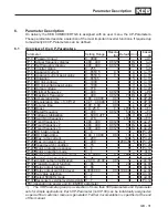
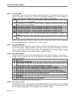
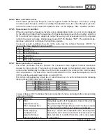
Страница 37: ...GB 37 Parameter Description...

Страница 38: ...the motor or frequency inverter e g evapo ration of capacitor electrolyte braise of the motor winding Monthly Check unit for loose screws and plugs and if necessary tighten up Clean frequency inverte...

Страница 39: ...ct variable transformer to inverter input Increase variable transformer slowly to indicated input voltage 1min and remain at least on the specified time Voltage class Input voltage Residence time 400V...

Страница 40: ...esidential areas In this case the operator may need to take cor responding measures B 1 2 UL Marking in preparation B 2 Further informations and documentation You find supplementary manuals and instru...

Страница 41: ...GB 41 Notes...

Страница 42: ...nfo keb fr KEB UK Ltd 6 Chieftain Buisiness Park Morris Close Park Farm Wellingborough GB Northants NN8 6 XF fon 44 1933 402220 fax 44 1933 400724 net www keb uk co uk mail info keb uk co uk KEB Itali...

Отзывы: