


|
keatingofchicago.com
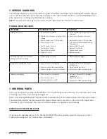
SERVICE DIAGNOSIS
The following diagnosis is only to be used as a guide to qualifi ed service personnel. Keating recommends that you
use a qualifi ed & licensed service company. (Equipment still under warranty requires it.) Call 1-800-KEATING if you
need assistance in locating a qualifi ed service company.
NOTE:
To correctly and quickly diagnose the system, the chart below should be followed in sequential order.
TROUBLE SHOOTING CHART
PROBLEM
PROBABLE CAUSE
SOLUTION
Griddle won't heat
a. No electricity to griddle.
b. Griddle circuit breakers (external) have
tripped.
c. On/Off switch is on "OFF" position.
d. Thermostat isn't on.
e. On/Off switch is faulty.
f. Thermostat is faulty.
g. Connections are loose.
h. Element is faulty.
a. Connect griddle to an approved source
of power.
b. Reset circuit breakers (external).
c. Set On/Off switch to 'ON" position.
d. Turn thermostat to desired cooking
temperature.
e. Replace On/Off switch.
f. Replace thermostat.
g. Tighten connections.
h. Replace element.
Indicating light does not illuminate
although element is heating
a. Indicating light is faulty.
a. Replace indicating light.
Temperature of griddle is erratic
a. Thermostat out of calibration.
b. Thermostat bulb improperly placed.
c. Exhaust problems or drafts in kitchen.
a. Calibrate thermostat. See page 7 –
Calibration.
b. Adjust thermostat bulb.
c. Contact your HVAC representative.
Griddle is overheating
a. Thermostat out of calibration.
b. Thermostat is faulty.
c. Improper exhaust or draft.
a. Calibrate thermostat. See page 7 –
Calibration.
b. Replace thermostat.
c. Contact your HVAC representative.
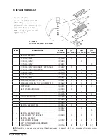
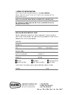
ORDERING PARTS
Parts may be ordered by calling 1-800-KEATING or your local Keating service company. You may also order on-line
at Keating’s part store, www.keatingofchicago.com
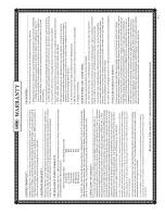
Refer to the Keating MIRACLEAN® Electric Griddle Limited Warranty for complete service and ordering information.
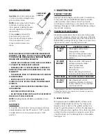
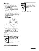
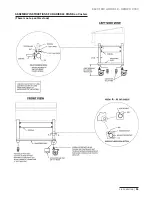
The model/serial plate is located inside of the grease drawer area to the left or on the front of the upper heat
shield above the control panel. The serial and model numbers are necessary when ordering.
WARNING AND OPERATING PLATES
All warning and operating plates on the Keating MIRACLEAN® Electric Griddle should be in place at all times.
If plates are damaged or lost, replace them immediately.
8
Содержание miraclean 2000 series
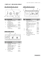
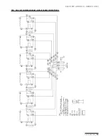
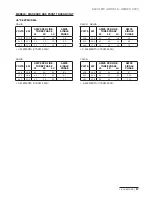
Страница 14: ...keatingofchicago com 12 208 240 VOLT WIRING DIAGRAM 3 PHASE CONNECTIONS...
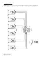
Страница 15: ...1 800 KEATING ELECTRIC GRIDDLE SERIES 2000 13 208 240 VOLT WIRING DIAGRAM SINGLE PHASE CONNECTIONS...
Страница 20: ......
Страница 21: ......


