


© Copyright 2019 KE2 Therm Solutions, Inc., Washington, Missouri 63090
Q.2.60 March 2019
Page 20
KE2 Compressor
Sequencer OEM
pn 21768
Quick Start Guide
When applying the controller to a system consisting of fixed speed
compressors with or without unloading capabilities, the controller
requires the user to assign a relay output for each compressor stage
available using the controller’s browser interface.
When Fixed Suction Pressure and only Fixed Speed Compressors
are selected the controller will stage the compressors by capacity in
HP as defined on the Setpoints page or Aux Relay Board Setpoints
page. Stages will be loaded and unloaded based on the smallest ca-
pacity step available. If all available stages are equal, the controller
will automatically select the option with the least amount of runtime.
The Suction Pressure Setpoint is the target pressure the controller
works to achieve while running. The Suction Pressure Differential
determines the pressure above and below the Suction Pressure
Setpoint the controller will allow the suction pressure to vary before
it makes an adjustment to capacity.
Once a stage has been loaded or unloaded, that stage must remain
on or off as determined by the Min Comp Runtime and Min Comp
Offtime. The controller will not load or unload more often than the
time defined in the Min Compressor Switch Time.
If the system is maintaining the suction pressure within the normal
operating range, which is defined as the Suction Pressure Setpoint
+/- the Suction Pressure Differential, it will maintain the current
capacity.
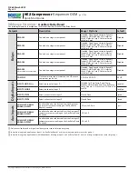
Mode of Control:
Fixed Suction Pressure & Fixed
Speed Compressors
Determining Compressor ON/OFF Order
Mode of Control:
Fixed Suction Pressure with
Digital Scroll or Variable
Speed Compressors
When applying the controller to a system consisting of fixed speed
compressors with or without unloading capabilities and one digital
scroll or variable speed compressor, the controller requires the user
to assign a relay output for each compressor stage available using the
controller’s browser interface.
The Digital Scroll or variable speed compressor will serve as the pri-
mary stage to provide the most consistent suction pressure possible.
Initially, the Digital Scroll will start unloaded, or the variable speed
compressor will run at the Min Speed setpoint.
If suction pressure rises above the Suction Pressure Setpoint, the
Digital Scroll will be loaded by de-energizing the bypass solenoid
or the variable speed compressor will be loaded by increasing the
0-10VDC output (0-5VDC also available). The rate at which the Digi-
tal Scroll or variable speed is loaded is determined by the controller’s
algorithm, and will improve as the controller learns the system. If the
Digital Scroll or variable speed compressor is fully loaded, the next
stage will be loaded based on the smallest capacity step available. If
all available stages are equal, the controller will automatically select
the option with the least amount of runtime. The compressors will
continue to be loaded until all compressors are running at full load.
If suction pressure falls below the Suction Pressure Setpoint, the
Digital Scroll will be unloaded by energizing the bypass solenoid, or
the variable speed compressor will be unloaded by decreasing the
0-10VDC output. If the Digital Scroll or variable speed compressor is
fully unloaded, the next stage will be unloaded based on the smallest
step available. If all available stages are equal, the controller will au-
tomatically select the option with the most amount of runtime. Suc-
tion pressure will primarily be controlled by loading and unloading
the Digital Scroll or variable speed compressor. If suction pressure is
still low, and all other stages have been unloaded, the Digital Scroll’s
compressor relay will be de-energized if minimum run, off and switch
times have been met. For variable speed compressors, the 0-10VDC
output will unload down to the Min Speed setpoint
①
.
①
The Digital Scroll and variable speed compressor’s requirements for
unloading follow their own rulesets and are not adjustable. It has been
designed to be within the limits of the compressor manufacturer, and to
ensure that specification is maintained the minimum times for transi-
tioning are not adjustable.
The KE2 Compressor Sequencer OEM has the ability to float the tar-
get suction pressure for maximum efficiency. When the Fixed/Float
Suction setpoint is set to Float Suction, all Room Temperature sen-
sors connected to a group will be compared to the Room Temp set-
point on the controller. When the average of the Room Temperature
sensors is below the Room Temp setpoint and above saturation tem-
perature, the controller will raise the target suction pressure. When
the average of the Room Temperature sensors is above the Room
Temp setpoint, the controller will lower the target suction pressure.
While floating suction is enabled, the Suction Pressure setpoint be-
comes the minimum suction pressure that the controller will work to
maintain.
Mode of Control:
Floating Suction Control


