Thrulink Operations Manual
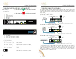
THRULINK PHYSICAL DETAILS – HIGH CAPACITY
HIGH CAPACITY
5
Thrulink Operations Manual
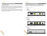
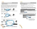
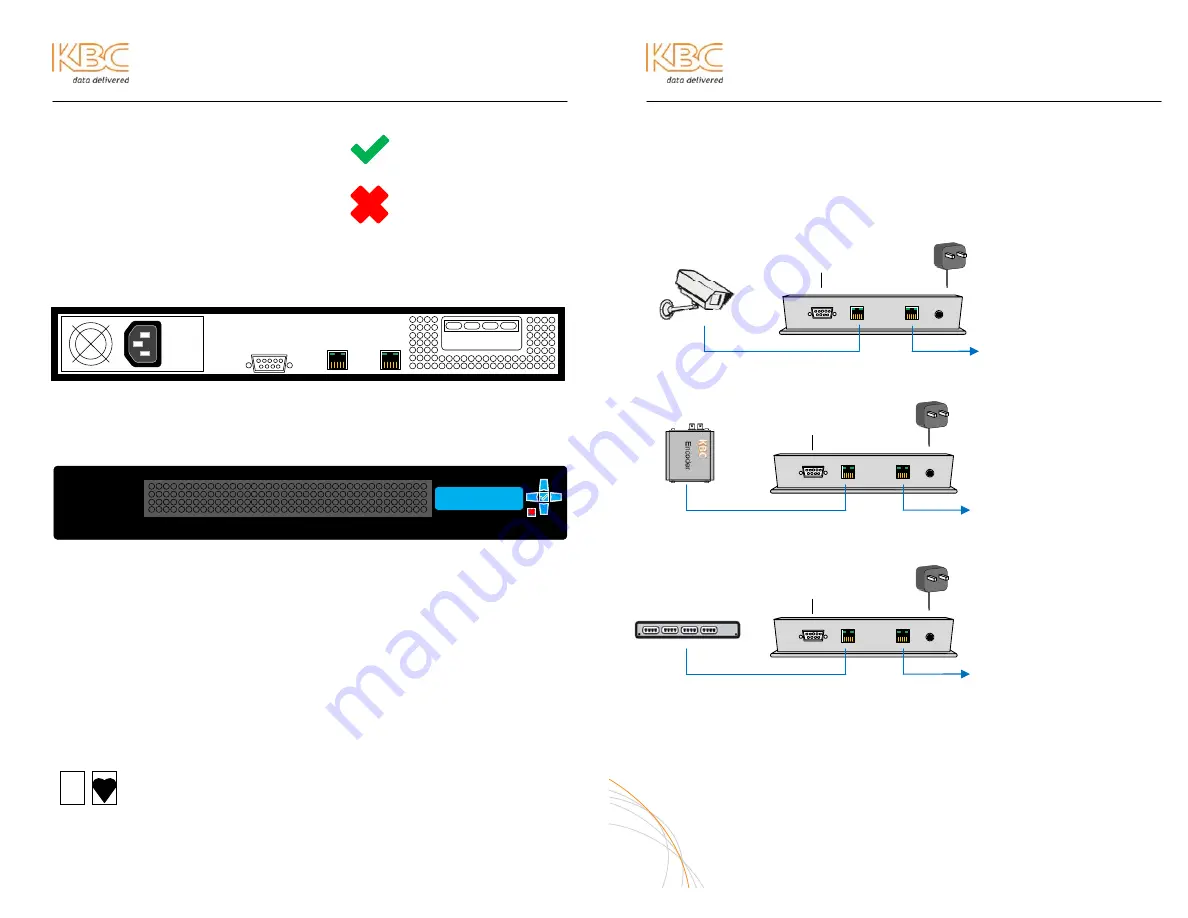
THRULINK CONNECTION DIAGRAM
The following wiring schemes represent the configuration that has been tested and
verified by KBC based on typical Ethernet wiring solutions. Other wiring configurations
could be possible based on the application. A bench test is recommended to verify the
design below.
CONNECTING TO AN IP CAMERA
CONNECTING TO A KBC ENCODER OR DECODER
CONNECTING TO AN ETHERNET 10/100/1000 SWITCH
* Type of Ethernet cable is determined by the Ethernet device LAN port. If the LAN port
is a 10/100 port then the connection may require a crossover cable. If the port is a
gigabit connection then a straight-through cable should be used. KBC recommends that
both types of cables are on hand in case your particular device requires a different
configuration than what KBC has tested.
6
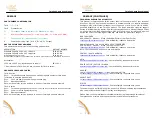
A. REAR VIEW
1.
Fan
2.
Power Input Port
3.
Serial Connection
4.
WAN port
5.
LAN port
B. FRONT VIEW
6.
LCD Display
7.
Power (Off). Hold for two seconds
8.
Power (On). Hold for two seconds
12 VDC
PS
Ethernet Cat5 or 6 cable* connect to network
Ethernet Cat5 or 6 cable*
To PC serial port
(for serial diagnostics or set up)
12 VDC
PS
Straight-through Cat5 cable
To PC serial port
(for serial diagnostics or set up)
Ethernet Cat5 or 6 cable* connect to network
12 VDC
PS
Straight-through Cat5 cable
To PC serial port
(for serial diagnostics or set up)
Ethernet Cat5 or 6 cable* connect to network
C. DIGITAL DISPLAY
KBC Networks, Ltd.
Boot up screen
Amount of load on the server in bytes
11 12
13
10
15
14
To turn on: Hold button for two seconds.
To turn off: Hold button for two seconds.
2
1
3 4
5
6
7 8
NetLoad (Bytes)
CPU: 123456a-b
CPU ID
Heart rate. Used to show unit is active


