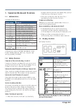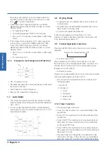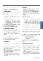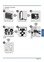
Installation
Page 43
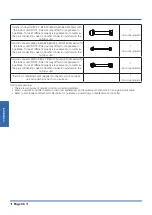
•
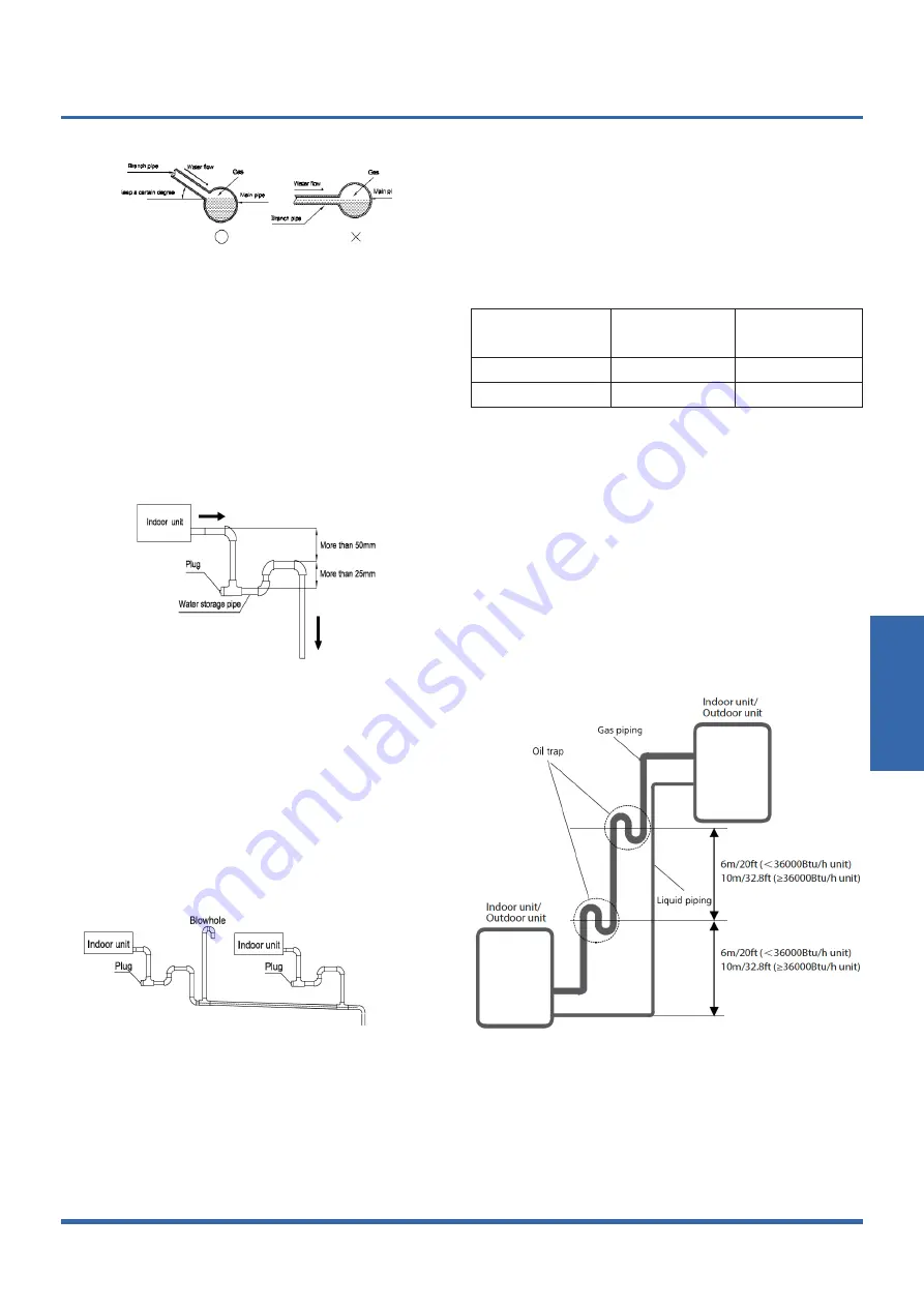
The correct installation will not cause converse
water flow and the slope of the branch pipes can be
adjusted freely
•
The false installation will cause converse water flow
and the slope of the branch pipe can not be ad-
justed.
6. Water storage pipe setting
•
If the indoor unit has high extra static pressure and
without water pump to elevate the condensate wa-
ter, such as high extra static pressure duct unit , the
water storage pipe should be set to avoid converse
flow or blow water phenomena.
8. Blowhole setting
•
For the concentrated drainage pipe system, there
should design a blowhole at the highest point of
main pipe to ensure the condensate water discharge
smoothly.
•
The air outlet shall face down to prevent dirt enter-
ing pipe.
•
Each indoor unit of the system should be installed it.
•
The installation should be considering the conve-
nience for future cleaning.
9. The end of drainage pipe shall not contact with ground
directly.
5.3 Insulation work of drainage pipe
Refer the introduction to the insulation engineering
parts.
6. Refrigerant Pipe Installation
6.1 Maximum length and drop height
Ensure that the length of the refrigerant pipe, the number
of bends, and the drop height between the indoor and
outdoor units meets the requirements shown in the
following table.
Capacity(k
Btu/h
)
Max. Length
(m/ft)
Max. Elevation
(m/ft)
12
25/82
10/32.8
18
30/98.4
20/65.6
caution:
• The capacity test is based on the standard length and
the maximum permissive length is based on the system
reliability.
• Oil traps
-If oil flows back into the outdoor unit’s compressor, this
might cause liquid compression or deterioration of oil
return. Oil traps in the rising gas piping can prevent this.
-An oil trap should be installed every 6m(20ft) of vertical
suction line riser (<36000Btu/h unit).
-An oil trap should be installed every 10m(32.8ft) of
vertical suction line riser (≥36000Btu/h unit).
6.2 The procedure of connecting pipes
1.Choose the pipe size according to the specification table.
2.Confirm the cross way of the pipes.
3.Measure the necessary pipe length.
Содержание KSDA-35 DVR14
Страница 7: ...Specifications Page 7 3 Dimensional Drawings 3 1 Indoor Unit...
Страница 8: ...Specifications Page 8 3 2 Outdoor Unit KUE 35 DVR13...
Страница 9: ...Specifications Page 9 KUE 52 DVR13...
Страница 10: ...Specifications Page 10 4 Centre of Gravity KUE 35 DVR13 KUE 52 DVR13...
Страница 14: ...Specifications Page 14 KUE 35 DVR13 KUE 52 DVR13...
Страница 49: ......

