background image

 Installation

 Page 47 

10. Engineering of Electrical Wiring

10.1  Highlights of electrical wiring 

installation


All field wiring construction should be finished by 
qualified electrician.


Air conditioning equipment should be grounded ac-
cording to the local electrical regulations.


Current leakage protection switch should be in-
stalled.


Do not connect the power wire to the terminal of 
signal wire.


When power wire is parallel with signal wire, put 
wires to their own wire tube and remain at least 
300mm gap.


According to table in indoor part named “the speci-
fication of the power” to choose the wiring, make 
sure the selected wiring not small than the date 
showing in the table.


Select different colors for different wire according to 
relevant regulations. 


Do not use metal wire tube at the place with acid or 
alkali corrosion, adopt plastic wire tube to replace it.


There must be not wire connect joint in the wire 
tube If joint is a must, set a connection box at the 
place.


The wiring with different voltage should not be in 
one wire tube.


Ensure that the color of the wires of outdoor and 
the terminal No. are same as those of indoor unit 
respectively.


You must first choose the right cable size before 
preparing it for connection. Be sure to use H07RN-F 
cables. 

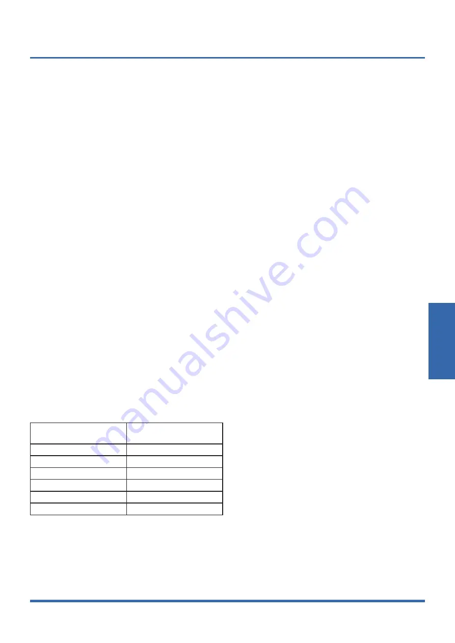
Table: Minimum Cross-Sectional Area able of Power and 
Signal Cables

Rated Current of  

Appliance (A)

Nominal Cross-Sectional 

Area(mm

2

)

≤ 6

0.75

6 - 10

1

10 - 16

1.5

16 - 25

2.5

25 - 32

4

32 - 45

6

11. Test Operation

11.1  The test operation must be carried out 

after the entire installation has been  
completed.

11.2  Please confirm the following points 

before the test operation.


The indoor unit and outdoor unit are installed prop-
erly.


Tubing and wiring are correctly completed.


The refrigerant pipe system is leakage-checked.


The drainage is unimpeded.


The ground wiring is connected correctly.


The length of the tubing and the added stow capac-
ity of the refrigerant have been recorded.


The power voltage fits the rated voltage of the air 
conditioner.


There is no obstacle at the outlet and inlet of the 
outdoor and indoor units.


The gas-side and liquid-side stop values are both 
opened.


The air conditioner is pre-heated by turning on the 
power.

11.3  Test operation

1. Open both the liquid and gas stop valves. 

2. Turn on the main power switch and allow the unit to 
warm up. 

3. Set the air conditioner to COOL mode, and check the 
following points.

Indoor unit


Whether the switch on the remote controller works 
well.


Whether the buttons on the remote controller 
works well.


Whether the air flow louver moves normally.


Whether the room temperature is adjusted well.


Whether the indicator lights normally.


Whether the temporary buttons works well.


Whether the drainage is normal.


Whether there is vibration or abnormal noise during 
operation.

Outdoor unit


Whether there is vibration or abnormal noise during 
operation.


Whether the generated wind, noise, or condensed 
of by the air conditioner have influenced your neigh-
borhood.


Whether any of the refrigerant is leaked.

Содержание KSDA-35 DVR14

Страница 1: ...UE 35 DVR13 KSDA 52 DVR14 KSD 52 DR14 KUE 52 DVR13 Double Flow Console TECHNICAL MANUAL Read this manual carefully before installing or operating your new air conditioning unit Make sure to save this...

Страница 2: ...ght Difference 10 Noise Criterion Curves 11 Electrical Characteristics 2 Product Features 28 1 Operation Modes and Functions 2 Remote Controller Functions 3 Installation 34 1 Installation Overview 2 L...

Страница 3: ...entre of Gravity 10 5 Electrical Wiring Diagrams 11 6 Refrigerant Cycle Diagrams 15 7 Air Velocity and Temperature Distributions 16 8 Capacity Tables 18 9 Capacity Correction Factor for Height Differe...

Страница 4: ...following table to determine the specific indoor and outdoor unit model number of your purchased equipment Indoor Unit Model Outdoor Unit Model Capacity Btu h Power Supply KSD 35 DR14 KUE 35 DVR13 12...

Страница 5: ...air flow Hi Mi Lo m3 h 650 580 490 780 690 600 Indoor sound pressure level dB A 37 34 27 41 38 32 Indoor sound power level dB A 54 55 Indoor unit Dimension W D H mm 794x206x621 794x206x621 Packing W D...

Страница 6: ...d quantity Kg 0 71 1 15 Design pressure MPa 4 3 1 7 4 3 1 7 Refrigerant piping Liquid side Gas side mm inch 6 35 9 52 1 4 3 8 6 35 12 7 1 4 1 2 Max refrigerant pipe length m 25 30 Max difference in le...

Страница 7: ...Specifications Page 7 3 Dimensional Drawings 3 1 Indoor Unit...

Страница 8: ...Specifications Page 8 3 2 Outdoor Unit KUE 35 DVR13...

Страница 9: ...Specifications Page 9 KUE 52 DVR13...

Страница 10: ...Specifications Page 10 4 Centre of Gravity KUE 35 DVR13 KUE 52 DVR13...

Страница 11: ...nit Abbreviation Paraphrase Y G Yellow Green Conductor CAP1 Indoor Fan Capacitor FAN Indoor Fan PUMP PUMP L LIVE N NEUTRAL TO CCM Comm Bus Central Controller T1 Indoor Room Temperature T2 Coil Tempera...

Страница 12: ...e controller To Remote Contol To Remote Alarm 3 YELLOW WHITE Y G RED N_IN BLACK INDOOR UNIT OUTDOOR UNIT 1 L 2 N L_IN S CN12CN42 INDOOR FAN2 M CN23 CN19 CN81 PLASMA LOWER OUTLET SWING MOTOR CN15 2 5 5...

Страница 13: ...COMP Compressor L PRO K2 Low Pressure Switch Shorting Stub K1 High Pressure Switch Shorting Stub TRANS Power Transformer T4 10K RESISTANCE Outdoor Ambient Temperature T3 10K RESISTANCE Coil Temperatu...

Страница 14: ...Specifications Page 14 KUE 35 DVR13 KUE 52 DVR13...

Страница 15: ...le Diagrams Model Pipe Size Diameter mm inch Piping length m ft Elevation m ft Additional Refrigerant Gas Liquid Rated Max Rated Max 12k 9 52 3 8 6 35 1 4 5 16 4 25 82 0 10 32 8 12g m 0 13oz ft 18k 12...

Страница 16: ...Specifications Page 16 7 Air Velocity and Temperature Distributions Discharge Angle 70 Upper 0 Lower Cooling airflow velocity distributions Cooling temperature distributions...

Страница 17: ...Specifications Page 17 Discharge Angle 20 Upper 0 Lower Heating airflow velocity distributions Heating temperature distributions...

Страница 18: ...90 3 90 3 90 4 19 4 19 4 19 4 19 S T 0 73 0 83 0 92 1 00 0 59 0 67 0 76 0 85 0 52 0 60 0 69 0 77 0 36 0 44 0 52 0 60 PI 0 70 0 70 0 70 0 70 0 69 0 69 0 69 0 69 0 69 0 69 0 69 0 69 0 69 0 69 0 69 0 69...

Страница 19: ...31 1 31 1 32 1 32 1 32 1 32 650 15 TC 3 84 3 87 3 90 3 93 4 02 4 02 4 02 4 05 4 12 4 12 4 12 4 12 4 40 4 40 4 40 4 40 S T 0 77 0 88 1 00 1 00 0 60 0 70 0 81 0 98 0 51 0 62 0 72 0 83 0 33 0 42 0 52 0 6...

Страница 20: ...22 4 22 4 22 4 22 S T 0 78 0 89 1 00 1 00 0 61 0 72 0 82 0 93 0 53 0 63 0 74 0 84 0 34 0 44 0 53 0 63 PI 1 90 1 90 1 90 1 90 1 91 1 91 1 91 1 91 1 91 1 91 1 91 1 91 1 93 1 93 1 93 1 93 690 15 TC 5 35...

Страница 21: ...08 1 08 1 09 1 09 1 09 1 09 20 TC 5 18 5 18 5 24 5 30 5 50 5 50 5 50 5 50 5 64 5 64 5 64 5 64 6 08 6 08 6 08 6 08 S T 0 75 0 85 0 95 1 00 0 59 0 69 0 79 0 88 0 52 0 61 0 71 0 80 0 35 0 44 0 52 0 61 PI...

Страница 22: ...7 0 3 17 3 14 3 12 3 12 1 36 1 41 1 38 1 38 5 6 3 21 3 18 3 16 3 16 1 32 1 33 1 33 1 34 2 8 3 24 3 21 3 18 3 18 1 24 1 25 1 25 1 26 0 0 3 24 3 21 3 18 3 16 1 18 1 18 1 18 1 18 2 8 3 36 3 30 3 27 3 27...

Страница 23: ...89 4 86 4 84 4 81 1 79 1 85 1 83 1 84 5 6 4 87 4 84 4 81 4 78 1 75 1 77 1 78 1 79 2 8 4 84 4 78 4 75 4 75 1 68 1 70 1 70 1 71 0 0 4 75 4 69 4 66 4 63 1 60 1 62 1 62 1 63 2 8 4 81 4 75 4 72 4 69 1 54...

Страница 24: ...8 0 970 0 1 000 0 993 0 978 0 970 Outdoor Upper than Indoor 5 0 992 0 985 0 970 0 962 10 0 977 0 962 0 955 Capacity Btu h 18K Pipe Length m Cooling 5 10 20 30 Height difference H m Indoor Upper than O...

Страница 25: ...lid at free field condition Data is valid at nominal operation condition Reference acoustic pressure OdB 20 Pa Sound level will vary depending on a range of factors such as theconstruction acousticabs...

Страница 26: ...at free field condition Data is valid at nominal operation condition Reference acoustic pressure OdB 20 Pa Sound level will vary depending on arrange off actors such as the construction acoustic absor...

Страница 27: ...40V 50Hz 220 240V 50Hz Power Wiring mm2 3 1 5 3 2 5 Circuit Breaker Fuse A 20 16 20 16 Indoor Outdoor Connecting Wiring Weak Electric Signal mm2 Strong Electric Signal mm2 4 1 0 4x2 5 with auxiliary e...

Страница 28: ...1 6 Heating Mode Heat pump models 30 1 7 Auto Mode 32 1 8 Drying Mode 32 1 9 Forced operation Function 32 1 10 Timer Function 32 1 11 Sleep Function 32 1 12 Auto Restart 33 1 13 8 C Heating 33 1 14 F...

Страница 29: ...operation Inverter module protection The inverter module has an automatic shutoff mechanism based on the unit s current voltage and temperature If automatic shutoff is initiated the corresponding err...

Страница 30: ...protective time Compressor running frequency is more than test frequency When compressor running frequency is equal to test frequency T4 is more than 15 C or T4 fault Change setting temperature Turbo...

Страница 31: ...pressor to cease operations 1 6 2 Indoor Fan Control 1 In heating mode the indoor fan operates continuously The fan speed can be set to 1 100 or low medium high and auto Anti cold air function The ind...

Страница 32: ...ing mode All protections are activated and operate the same as they do that in cooling mode Low Room Temperature Protection If the room temperature is lower than 10 C the compressor ceases operations...

Страница 33: ...not receive a signal for 7 minutes or you press Follow Me the function turns off The unit regulates temperature based on its own sensor and settings 1 15 Silence Press Silence on the remote control t...

Страница 34: ...stallation 39 4 Outdoor Unit Installation 41 5 Drainage Pipe Installation 42 6 Refrigerant Pipe Installation 43 7 Vacuum Drying and Leakage Checking 44 8 Additional Refrigerant Charge 45 9 Engineering...

Страница 35: ...ion sheath some models 2 Heat insulation pipe 1 Anchor 6 depending on models Mounting plate fixing screw 6 depending on models Copper nut 2 Hook 2 Drain joint some models 1 Seal ring some models 1 Mag...

Страница 36: ...alled on the outdoor unit 1 on some models Transfer connector 9 52 12 7 0 375in 0 5in Packed with the indoor unit NOTE Pipe size may differ from appliance to appliance To meet different pipe size requ...

Страница 37: ...llation Overview Installation Order Install the drainpipe Install the outdoor unit 1 2 3 4 5 MC MC 6 7 Install the indoor unit Evacuate the refrigeration system Connect the wires Connect the refrigera...

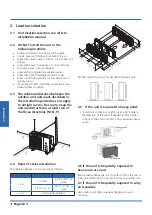
Страница 38: ...tight rooms Be sure to keep the unit unobstructed in at least two of the three directions M N P 2 4 Rows of series installation The relations between H A and L are as follows L A L H L 1 2H 25 cm 9 8...

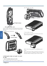
Страница 39: ...ions it is not necessary 2 Fix the mounting plate with a tapping screw onto the wall NOTE It is recommended to fx it on the wall according to the hanging hole indicated by the arrow on the mounting pl...

Страница 40: ...pipe 1 Open the bottom piping cover plate Press and hold the bottom two buckles and then rotate to open the piping cover plate Two buckles 2 Remove the cover plate Remove the pipe cover plate and inst...

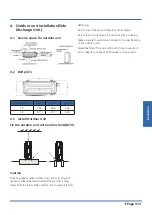
Страница 41: ...vity center of the unit is not at its physical center so please be careful when lifting it with a sling Never hold the inlet of the outdoor unit to prevent it from deforming Do not touch the fan with...

Страница 42: ...for reference PVC pipe Reference value of inner diameter of pipe mm Allowable maximum water flowrate l h Remark Slope 1 50 Slope 1 100 PVC25 20 39 27 For branch pipe PVC32 25 70 50 PVC40 31 125 88 Co...

Страница 43: ...act with ground directly 5 3 Insulation work of drainage pipe Refer the introduction to the insulation engineering parts 6 Refrigerant Pipe Installation 6 1 Maximum length and drop height Ensure that...

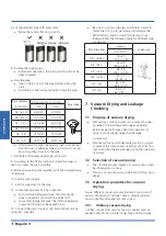
Страница 44: ...dinary vacuum drying 1 When conduct first vacuum drying connect pressure gauge to the infusing mouth of gas pipe and liquid pipe 4 Cut the selected pipe with pipe cutter Make the section flat and smoo...

Страница 45: ...lf an hour If the pressure reached 755mmHg start to pressure leakage test If it cannot reached the value repeat vacuum damage and vacuum drying again for 1 hour 4 Leakage test After the vacuum degree...

Страница 46: ...ipe shall be 5 10cm longer than the gap of the insulation mate rial The insulation material at the joint pipe shall be inserted into the gap of the insulation material The insulation material at the j...

Страница 47: ...10 1 10 16 1 5 16 25 2 5 25 32 4 32 45 6 11 Test Operation 11 1 The test operation must be carried out after the entire installation has been completed 11 2 Please confirm the following points before...

Страница 48: ...rn on the main power switch and run the air conditioner in COOL mode d Listen to the sound of the drain pump to see if it makes any unusual noises e Check to see that the water is discharged It may ta...

Страница 49: ......

Отзывы: