Page no. 13 | Error! Not a valid bookmark self-
reference.
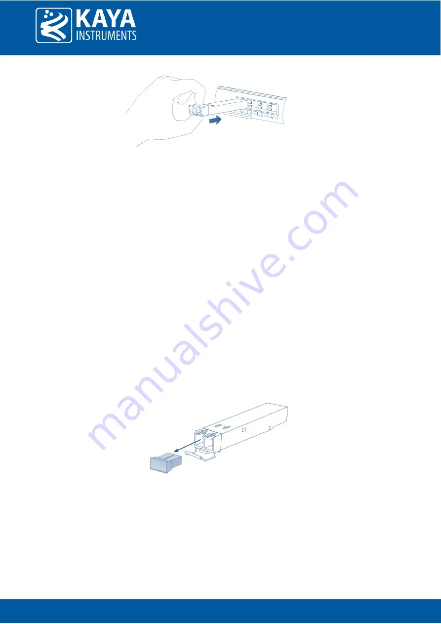
Figure 4 : Installing an SFP+ Module into a port
6.1.5
Connecting the interface cable to SFP+ Module
In order to properly connect the fiber optic cables, the following steps must be taken:
1.
Remove the dust cups from the module as shown in Figure 5.
2.
Remove the protective dust plugs from the fiber-optic cable connectors.
3.
Preform the connection according to the instructions below:
a.
A fiber cable should match an SFP+ type. If a single mode SFP+ is used a single mode fiber (yellow)
should be attached to it. If a multi-mode SFP+ is used a multi-mode fiber (orange) should be
attached.
b.
On Fiber channel 0 both the TX and RX fiber cables must be connected. On channels 1 through 3 only
one fiber cable should be connected. This cable is connected between TX output (Marked with TX or
Arrow outwards the SFP+) on the Camera Link Extender Device unit and RX input (Marked with RX or
Arrow inwards the SFP+) on the Camera Link Extender Host unit, as shown in Figure 6.
c.
Both the TX and RX fiber cables must be connected (for bidirectional communication, a single fiber
cable should be connected between TX and RX).
d.
If more than a single cable is used to connect to the same Camera Link Extender unit, the cables
must be of the same type and length.
4.
Insert the fiber cable into the module, as shown in Figure 7.
5.
Firmly push on each cable, until you will hear a click.
6.
Connect the other side of the fiber cable to the Camera Link Extender Host unit (KY-CL2F-H).
Figure 5 : SFP+ Module with bale clasp open and dust plug removed


