– 11 –
▼
▼ ▼
▼▼
▼▼
▼
Adjust screw A
Lock nut A
Lock nut B
Lock nut B
Adjust screw B
(Upper)
Adjust screw B
(Lower)
Indicator
(Guideline)
Adjusting
point
Adjusting
point
Adjusting
point
Adjusting
point
Adjusting
point
Read the number on the scale
This indicates “4.5”.
(Longer scale line means 0.5)
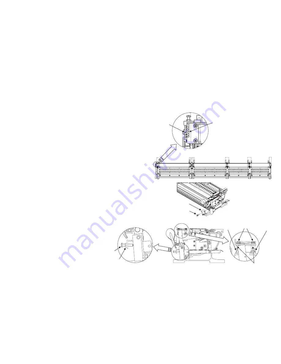
Figure 2
Figure 3
Figure 4
Screw for hammer rail
(attached here)
Rail positioning fitting
[Work Procedure] - Adjusting the stop rail height per section -
In the GP, the distance between the keybed and the string undersurfaces may vary depending on the
areas of the piano.
In the GP-ATX, it is possible to adjust the stop rail height per section to follow the variation of this
distance, and make sure that the muting happens at the 4 mm point of let-off.
This procedure should be implemented when the adjustment per section is needed if the muting works
only partially.
【B-8】
Using the jig, adjust by 4 mm the let-off of the keys at both ends of each section (8 keys in total).
* If the 4 mm jig is not available, adjust it by 4 mm by visual judgment using the 3 mm jig
instead.
【B-9】
Switch to the Silent Mode, and write down the value of the scale located at the bass side of the
stop rail, as shown in Figure 2.
【B-10】
Attach the rail positioning fitting on the action as shown in Figure 3.
* The rail positioning fitting is fixed with a screw at the treble side of the rear chambranle
(threshold, Kamachi).
* One screw for the hammer rail is attached at the bass side end of the action.
【B-11】
Loosen the lock nut A (Figure 4) and rotate the adjust screw A so that the scale indicator at the
bass side of the stop rail points to the value read in 【B-9】. Then tighten the lock nut A to fasten
the stop rail.
* By doing this, the height of the stop rail across the board becomes equal to that of when it was
in the piano.
【B-12】
Adjust the height of the stop rail aligning it to the let-off position of both ends of each section.
* There are eight areas to adjust as shown in Figure 2.
* Loosen the lock nut B (Figure 4) and adjust the height using the adjust screw B (Upper).
Rotate clockwise : Lower Rotate counterclockwise : Lift
* Adjust both forward and backward ends to make it parallel to the hammer shank.
Then rotate the adjust screw B (Upper) about one time per turn.
※ Especially for counterclockwise rotation, the adjust screw B (Upper) could drop off from the
adjust screw B (Lower).
If that happens, remove the adjust screw B (Upper) once and apply a slight coat of instant
glue on the screw hole of the adjust screw B (Lower) then tighten the adjust screw B (Upper).
* After completing the adjustment, tighten the lock nut B without changing the adjust position
of the adjust screw B (Lower).
【B-13】
Align the let-off of the remaining keys to the stop rail.
* Move the hammer shank at the let-off position as close as possible to the stop rail.
【B-14】
Remove the rail positioning fitting and fasten the stop rail at the original
position on the rear chambranle (threshold).
【B-15】
Put the action back into the piano and re-install keyslip, keyblock and
fallboard.
【B-16】
Check the muting state.
* Criteria for judging
・ Hit strongly each section of the keyboard five times in
a row with three fingers of your dominant hand, and
make sure that the hammer does not strike the string.
・ If the string was hit during the above, repeat the
procedure from 【B-8】 for re-adjusting.


